A kind of oil pollution cooling recovery device for CNC machine tool processing

A technology of cooling recovery device and CNC machine tool, which is applied in the direction of metal processing equipment, metal processing machinery parts, manufacturing tools, etc., can solve the problems of low efficiency of oil pollution recovery and waste of resources, so as to improve the efficiency of recovery treatment, avoid waste, and improve recovery efficiency effect

Active Publication Date: 2022-05-17
HANGZHOU VOCATIONAL & TECHN COLLEGE
View PDF4 Cites 0 Cited by
  • Summary
  • Abstract
  • Description
  • Claims
  • Application Information

AI Technical Summary

Problems solved by technology

[0004] The invention proposes an oil pollution cooling recovery device for CNC machine tools, which solves the problem of waste of resources caused by the low efficiency of oil pollution recovery in existing CNC machine tools

Method used


Image

  • A kind of oil pollution cooling recovery device for CNC machine tool processing
  • A kind of oil pollution cooling recovery device for CNC machine tool processing
  • A kind of oil pollution cooling recovery device for CNC machine tool processing

Examples


Embodiment 1

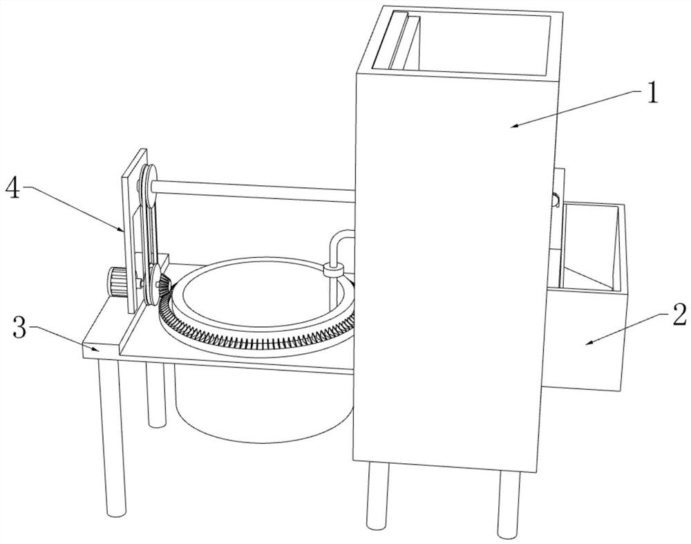
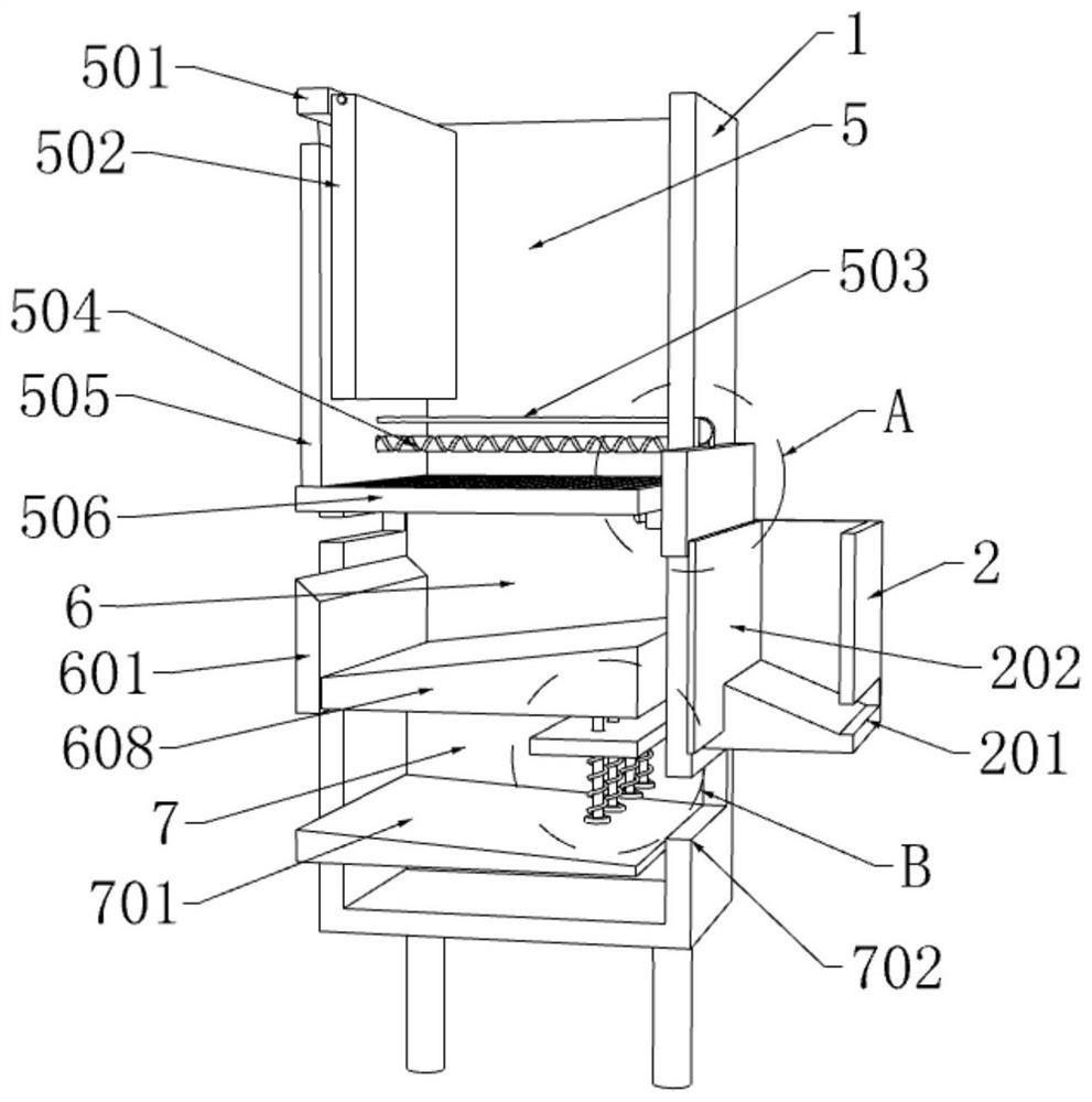
[0030] refer to Figure 1-4 , an oil pollution cooling recovery device for CNC machine tool processing, comprising a treatment box 1, the interior of the treatment box 1 is sequentially provided with a chip removal tank 5, a sedimentation tank 6 and a mud discharge tank 7 along its height direction;

[0031] A chip removal box 2 is fixedly installed on one side of the treatment box 1, and an oil-liquid separation mechanism 3 is provided on the side of the treatment box 1 away from the chip removal box 2, and a driving mechanism 4 is arranged on the top of the oil-liquid separation mechanism 3;

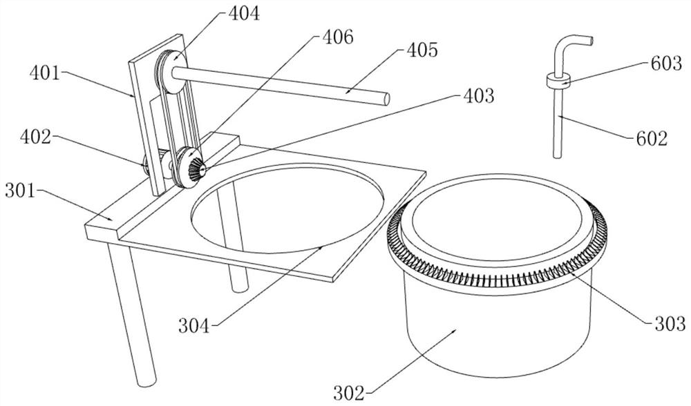
[0032] Drive mechanism 4 comprises support 401, drive motor 402, drive gear 403, secondary pulley 404, transmission rod 405 and primary pulley 406, and drive motor 402 and support 401 are all fixedly installed with the top of oil-liquid separation mechanism 3, and the top of drive motor 402 The output shaft is fixedly connected with a main pulley 406 and a driving gear 403, and the sid...

Embodiment 2

[0039] refer to Figure 2-5 A second baffle plate 601 arranged in a vertical direction is fixedly connected to the side of the sedimentation tank 6 close to the drive mechanism 4, and a moving plate 608 is fitted and slidably installed between the second baffle plate 601 and the inner wall of the sedimentation tank 6 , the top of the moving plate 608 is inclined, and the side of the sedimentation tank 6 away from the second baffle plate 601 is fixedly connected with a second fixed plate 605, and the plate body of the second fixed plate 605 slides along its length direction and is provided with Be the guide bar 606 of equidistant distribution, the top of guide bar 606 is fixedly connected with the bottom end of moving plate 608, and the bar body of guide bar 606 is provided with return spring 607, the top of return spring 607 and the second fixed plate 605 Fixed connection at the bottom.

[0040] The inner wall of the settling tank 6 is equipped with a liquid level sensor 604,...

Embodiment 3

[0044] refer to figure 1 and figure 2 The oil-liquid separation mechanism 3 includes a first fixed plate 301, a separation cylinder 302, a gear ring 303 and a limit groove 304, and the side of the processing box 1 away from the chip removal box 2 is fixedly connected with the first fixed plate 301 arranged horizontally, And the driving motor 402 and the bracket 401 are all fixedly installed on the top of the first fixed plate 301, the plate body of the first fixed plate 301 is provided with a circular limiting groove 304, and the inner rotation of the limiting groove 304 is equipped with a separate The cylinder 302 and the outer wall of the separation cylinder 302 are fixedly sleeved with a gear ring 303 , the gear ring 303 is located above the first fixing plate 301 , and the driving gear 403 meshes with the tooth block on the gear ring 303 .

[0045] The side of the treatment box 1 far away from the chip removal box 2 is provided with a drainage port, and the drainage port...


PUM


Abstract

The invention discloses an oil pollution cooling recovery device for CNC machine tool processing, which relates to the field of CNC machine tools. Aiming at the problem of waste of resources caused by the low efficiency of oil pollution recovery in existing CNC machine tools, the following scheme is proposed, which includes a processing box, and the processing The inside of the box is provided with a chip removal tank, a sedimentation tank and a mud discharge tank in sequence along its height direction, a chip removal box is fixedly installed on one side of the treatment box, and an oil tank is installed on the side of the treatment box away from the chip removal box. The top of the oil-liquid separation mechanism is provided with a drive mechanism, and the drive mechanism includes a bracket, a drive motor, a drive gear, a secondary pulley, a transmission rod and a primary pulley. The invention can effectively remove swarf, desilt and centrifugal stratify the cooling oil used in machine tool processing, effectively improve the recovery efficiency of the cooling oil, and at the same time avoid the blockage of the return pipe caused by the recovery of the cooling oil .

Description

technical field [0001] The invention relates to the field of numerically controlled machine tools, in particular to an oil pollution cooling recovery device for machining of numerically controlled machine tools. Background technique [0002] CNC machine tool is the abbreviation of numerical control machine tool, which is an automatic machine tool equipped with a program control system. The control system can logically process programs with control codes or other symbolic instructions, decode them, express them in coded numbers, and input them into the numerical control device through the information carrier. After calculation and processing, various control signals are sent by the numerical control device to control the movement of the machine tool, and the parts are automatically processed according to the shape and size required by the drawing. CNC machine tools solve complex, precise, small-batch, and multi-variety parts processing problems. It is a flexible, high-effici...

Claims


Application Information

Patent Timeline
Patent Type & Authority Patents(China)
IPC IPC(8): B23Q11/10
CPCB23Q11/1069Y02P70/10
Inventor 丁媛媛刘涵金寅德
Owner HANGZHOU VOCATIONAL & TECHN COLLEGE
Why Eureka
Try Eureka