
Explosion-proof emergency treatment device for fire-fighting spray header
An emergency treatment and sprinkler technology, applied in fire rescue and other directions, can solve the problem that buckets cannot be completely collected, and achieve the effect of avoiding water splashing
- Summary
- Abstract
- Description
- Claims
- Application Information
AI Technical Summary
Problems solved by technology
Method used
Image

Examples
Embodiment 1
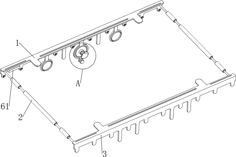
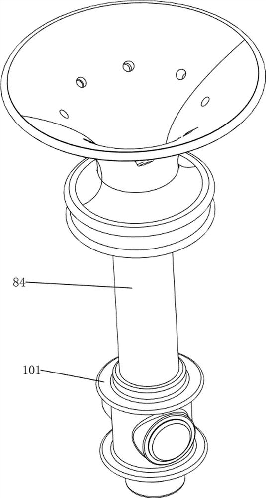
[0037] A fire sprinkler head explosion-proof emergency treatment device, such as Figure 1-17 As shown, it includes a first mounting plate 1, a connecting rod 2, a second mounting plate 3, a first fixing column 4, a buzzer 5, a humidity sensor 6, a transposition mechanism 7 and a lifting mechanism 8. The first mounting plate 1 The left and right sides of the front side are provided with connecting rods 2, the second mounting plate 3 is connected between the front sides of the connecting rods 2, the first fixing column 4 is arranged in the middle of the bottom of the first mounting plate 1, and the first fixing column 4 is provided with The buzzer 5 and the humidity sensor 6, the humidity sensor 6 is located at the lower side of the buzzer 5, a transposition mechanism 7 is connected between the first mounting plate 1 and the second mounting plate 3, the first mounting plate 1 and the transposition mechanism 7 A rising mechanism 8 is connected between them.
[0038]The transpos...
PUM
 Abstract
Description
Claims
Application Information