

Tubular heat exchanger
A technology of tube-and-tube heat exchanger and heat exchange tube, which is applied in the direction of heat exchanger type, indirect heat exchanger, heat transfer modification, etc., and can solve the problem of low cleaning cost, poor cleaning effect, and heat source of lower side baffles. Liquid can not be discharged and other problems to achieve the effect of increasing the flow rate and speeding up the flow speed
- Summary
- Abstract
- Description
- Claims
- Application Information
AI Technical Summary
Problems solved by technology
Method used
Image

Examples
Embodiment Construction
[0015] In order to make the purpose, technical solutions and advantages of the embodiments of the present invention clearer, the technical solutions in the embodiments of the present invention will be clearly and completely described below in conjunction with the drawings in the embodiments of the present invention. Obviously, the described embodiments It is a part of embodiments of the present invention, but not all embodiments. Based on the embodiments of the present invention, all other embodiments obtained by persons of ordinary skill in the art without creative efforts fall within the protection scope of the present invention.
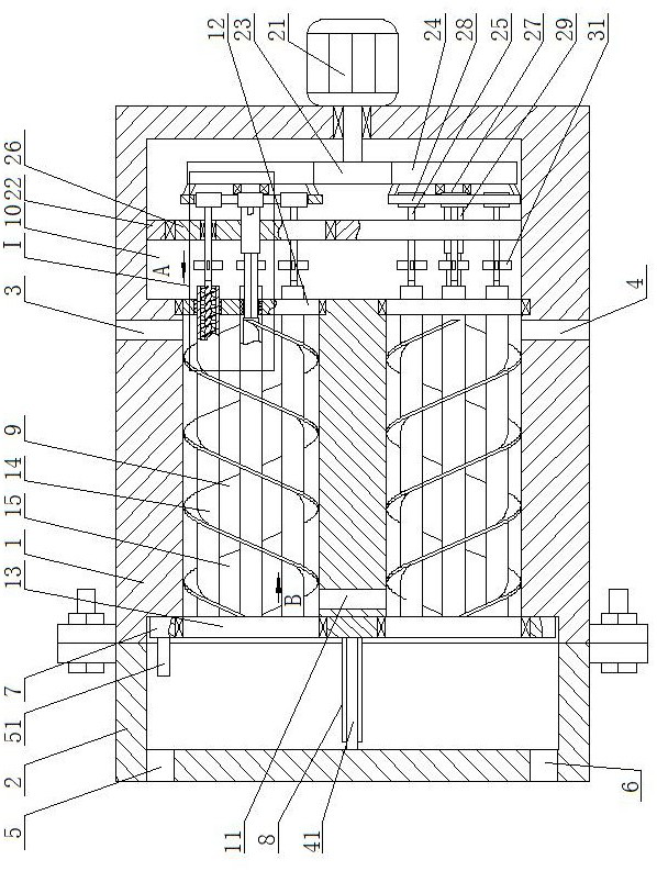
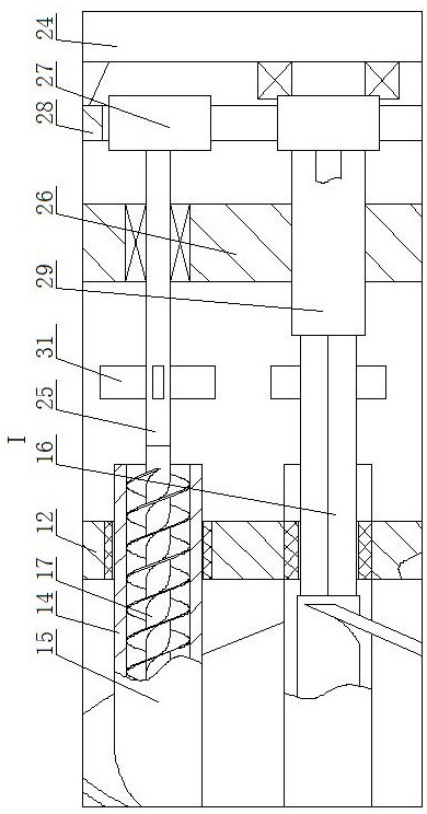
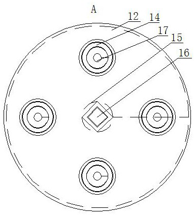
[0016] A shell and tube heat exchanger, such as Figure 1-4As shown, it includes a shell 1 and a shell cover 2. The left side of the shell 1 is open. The shell 1 and the shell cover 2 are connected by a bolt structure. The shell 1 is provided with a heat source inlet 3 and a heat source outlet 4. The shell The cover 2 is provided with a cold sour...
PUM
 Abstract
Description
Claims
Application Information