Sensor for identifying tubing coupling

A sensor and hall sensor technology, applied in the field of sensors for identifying oil pipe couplings, to achieve accurate and reliable test results, ensure stability, and strong signal anti-interference ability

Pending Publication Date: 2022-03-11
贵州航天凯山石油仪器有限公司
View PDF0 Cites 0 Cited by
  • Summary
  • Abstract
  • Description
  • Claims
  • Application Information

AI Technical Summary

Problems solved by technology

[0005] The invention provides a sensor for identifying oil pipe couplings to solve the technical problem of plunger type testing instruments identifying oil pipe couplings

Method used


Image

  • Sensor for identifying tubing coupling
  • Sensor for identifying tubing coupling
  • Sensor for identifying tubing coupling

Examples


Embodiment

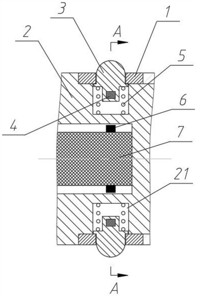
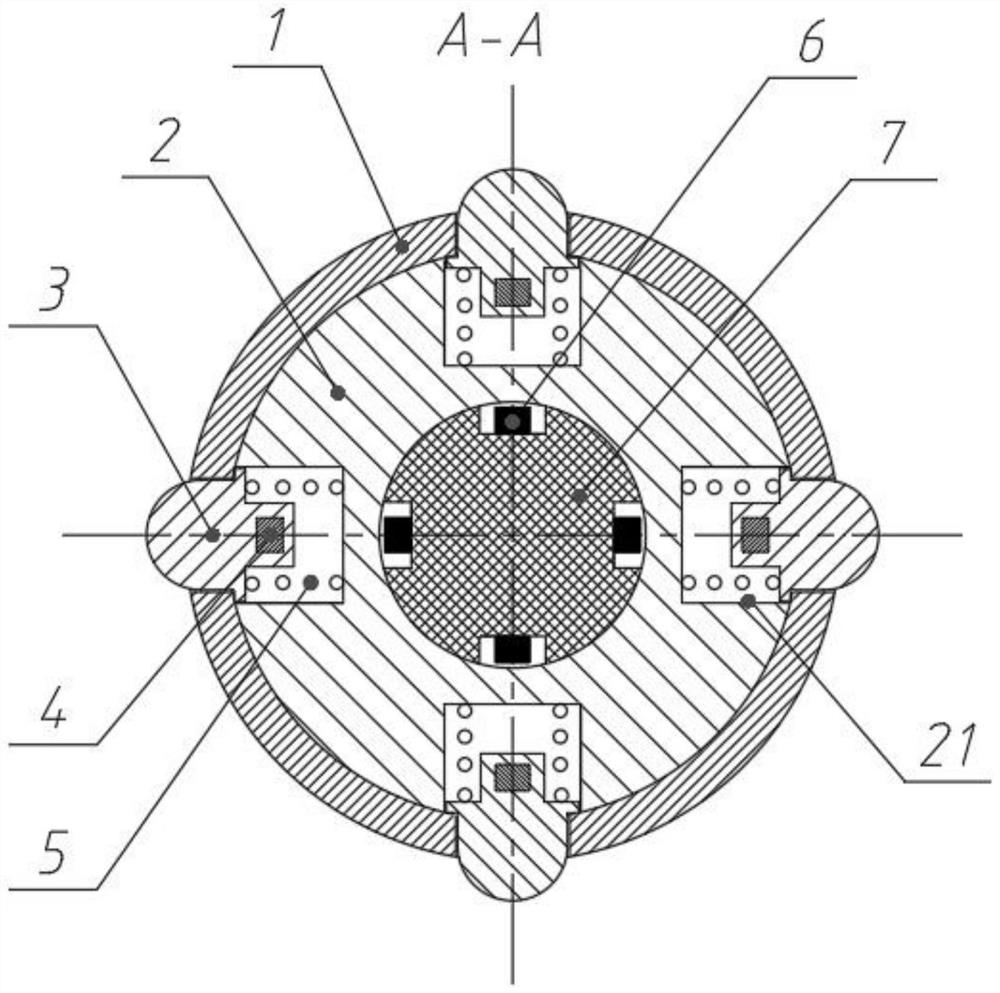
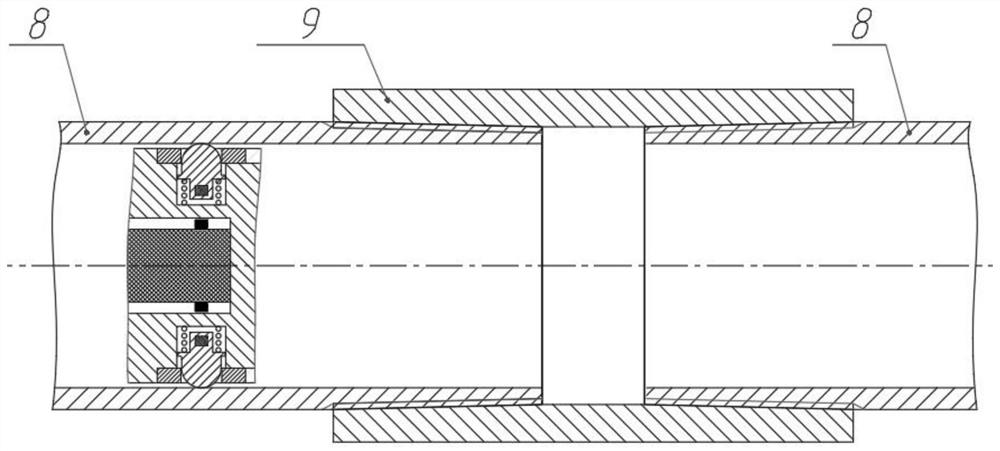
[0024] refer to Figure 1 to Figure 4 , this embodiment provides a sensor for identifying oil pipe couplings, including a mounting base 2 that is circumferentially sleeved and fixed with a limit sleeve 1, the mounting base 2 is a cylindrical structure made of non-magnetic steel, and the limit sleeve 1 is a circular ring that is tightly sleeved and fixed on the outer surface of the installation base 2. The middle part of the installation base 2 has a hole and a built-in sensor mounting seat 7. Four Hall sensors are fixed on the sensor mounting seat 7 at equal intervals along the circumferential direction. 6. The outer side of the installation base 2 is provided with four grooves 21 in one-to-one correspondence with the Hall sensor 6 along the circumferential direction, and each groove 21 is correspondingly equipped with a movable switch 3, and one end of the movable switch 3 Through the limiting sleeve 1 and extending to the outside of the limiting sleeve 1, the other end of th...


PUM


Abstract

The invention provides a sensor for identifying a tubing coupling, which comprises a mounting base sleeved and fixed with a limiting sleeve in the circumferential direction, a hole is formed in the middle of the mounting base, a sensor mounting seat is arranged in the hole, a plurality of Hall sensors are distributed and fixed on the sensor mounting seat in the circumferential direction, and a plurality of grooves corresponding to the Hall sensors are formed in the outer side of the mounting base in the circumferential direction. Each groove is internally and correspondingly provided with a movable switch, one end of each movable switch penetrates through the limiting sleeve and extends to the outer side of the limiting sleeve, the other end of each movable switch is provided with a limiting shoulder so as to be clamped in the corresponding groove in a limiting mode, a spring is arranged between each movable switch and the bottom of the corresponding groove in a pressing mode, and magnetic steel is further fixed to the other end of each movable switch. The technical problem that a plunger type testing instrument recognizes the tubing coupling is solved. Belongs to the technical field of gas well underground testing instruments.

Description

technical field [0001] The invention relates to a sensor for identifying oil pipe couplings, which belongs to the technical field of downhole testing instruments for gas wells. Background technique [0002] The tubing collar is the connecting joint between the downhole tubing. Since the length of a single tubing is fixed, the number of tubing in the wellbore is fixed, and the total depth of the tubing is fixed, the testing instrument can accurately convert a period of time by identifying the coupling time of the tubing coupling and other parameters. Data such as the distance traveled by the instrument, the average speed, and the depth and position of the tubing at the time of the test. Therefore, how to accurately identify tubing couplings has become an important technology required for instruments that test parameters such as depth and moving distance. [0003] In the past, magnetic positioning technology was commonly used in instruments to identify tubing couplings. Accor...

Claims


Application Information

Patent Timeline
Patent Type & Authority Applications(China)
IPC IPC(8): E21B47/092
CPCE21B47/092
Inventor 汪开义龙志祥
Owner 贵州航天凯山石油仪器有限公司
Why Eureka
Try Eureka