After-drilling reamer capable of preventing blade pin shaft from falling

A technology of eye reamer and blade, which is applied in the direction of drill bit, earthwork drilling, drilling equipment, etc. It can solve the problems of pin sticking, easy falling off of pin shaft, etc., and achieve the effect of preventing prolapse or breaking and reducing the probability of complicated situations

Pending Publication Date: 2022-05-27
中石化石油工程技术服务有限公司 +3
View PDF0 Cites 0 Cited by
  • Summary
  • Abstract
  • Description
  • Claims
  • Application Information

AI Technical Summary

Problems solved by technology

[0005] The purpose of the present invention is to provide a post-drilling reamer that prevents the pin shaft from falling off in order to solve the problem that the pin shaft of the existing reamer structure is easy to fall off during downhole use, specifically a detachable baffle plus The screw fixing device can ensure that during the long-term construction of the reamer, the pin shaft will not fall out of the tool body and fall into the well, ensuring the safety of underground construction
Solved the problem of stuck pipe caused by pin shaft falling in the past

Method used


Image

  • After-drilling reamer capable of preventing blade pin shaft from falling
  • After-drilling reamer capable of preventing blade pin shaft from falling
  • After-drilling reamer capable of preventing blade pin shaft from falling

Examples


Embodiment 1

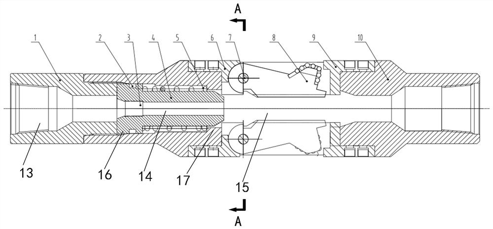
[0025] A post-drilling reamer with blades 8 pins 7 falling off, including an upper joint 1, a main body 10, a blade 8, a piston 4, a spring 5, a nozzle 3, one end of the main body 10 is connected with the upper joint 1, and the main body 10 is provided with The installation hole of the blade 8, the blade 8 is installed in the installation hole of the blade 8 through the pin 7, the upper joint 1 is provided with a first center hole 13, the body 10 is provided with a second center hole 15, the piston 4 is slidably sleeved in the second central hole 15, the left end face of the piston 4 is in contact with the right end face of the upper joint 1, the right end face of the upper joint 1 restricts the leftward sliding of the piston 4, and a third central hole 14 is arranged inside the piston 4. A central hole 13, a second central hole 15, and a third central hole 14 communicate with each other. The third central hole 14 is provided with a nozzle 3. The nozzle 3 is located at the left...

Embodiment 2

[0035] refer to figure 1, in the figure, the piston 4 and the spring 5 are placed in the body 10 together. When installing, use a special auxiliary tool to press the piston 4 down a certain distance, so that the lower groove of the piston 4 is exposed at the slot position of the blade 8, and then the blade 8 is installed. Insert into the main body 10, penetrate the pin shaft 7 to fix the blade 8 on the main body 10, install the support block 6 and the second limit block 9, and use screws to fix it. After the drilling fluid is injected into the tool, a pressure difference is generated at the position of the water hole of the piston 4, which pushes the piston 4 to go down, and the piston 4 pushes the blade 8 to expand outward at the same time. When the drilling tool rotates, the formation can be cut, and the steps are first built. When the three blades 8 are stretched to the maximum outer diameter under the action of the thrust of the piston 4, the steps are completed. At this t...


PUM


Abstract

The invention relates to the technical field of drilling engineering, in particular to an after-drilling reamer capable of preventing a blade pin shaft from falling off. Comprising an upper connector, a body, a blade, a piston, a spring and a nozzle, the blade is arranged on the body through a pin shaft, the piston is arranged in the body in a sleeved mode, the spring is arranged on the piston in a sleeved mode, the blade is pushed through the piston to conduct reaming operation, and a first shaft hole and a second shaft hole which are used for installing the pin shaft are formed in the body. The second shaft hole is a stepped hole composed of a large hole and a small hole, the two ends of the pin shaft are inserted into the first shaft hole and the large hole respectively, one end of the pin shaft is matched with the limiting part in a limiting mode, and the other end of the pin shaft is matched with the small hole in a limiting mode. The diameter of the first shaft hole is equal to that of the large hole, and the diameter of the small hole is smaller than that of the pin shaft. The stress of the pin shaft fixing screw is changed through the detachable baffle, the fixing screw is prevented from being disengaged or fractured, the blade pin shaft cannot be disengaged from the body in the drilling process and the reaming construction process, and the probability that complex conditions occur underground is reduced.

Description

technical field [0001] The invention relates to the technical field of drilling engineering, in particular to a post-drilling reamer with a blade pin shaft prevented from falling off. Background technique [0002] With the increase of complex drilling such as deep wells, small wells and casing sidetracking, in order to increase the gap between the casing and the well wall annulus and improve the cementing quality of this type of well, the downhole reaming operation is very important. Especially the reaming operation of the small wellbore section in the lower part of deep wells and ultra-deep wells. The supporting technology of downhole reaming is the technical basis and preparation for developing the expansion pipe technology in the future. For open hole completion, downhole reaming technology can increase the exposed area of ​​the oil reservoir and improve the oil recovery factor. Through downhole reaming technology, unconventional wellbore structure (casing level) can be...

Claims


Application Information

Patent Timeline
Patent Type & Authority Applications(China)
IPC IPC(8): E21B7/28E21B10/32E21B10/61E21B10/633
CPCE21B7/28E21B10/322E21B10/633E21B10/61
Inventor 王卫张辉李春光刘志和陈忠帅陈勇赵传伟陈锐刘峰于文涛庄伟宁仁磊赵宗锋
Owner 中石化石油工程技术服务有限公司
Why Eureka
Try Eureka