Mounting structure for spindle unit of numerical control machine tool

A technology of installation structure and CNC machine tools, which is applied in the direction of metal processing equipment, etc., can solve problems such as assembly errors, low assembly efficiency, and easily limited operating space, and achieve the effect of increasing the force-bearing area and maintaining stability

Pending Publication Date: 2022-07-08
安徽新诺精工股份有限公司
View PDF0 Cites 0 Cited by
  • Summary
  • Abstract
  • Description
  • Claims
  • Application Information

AI Technical Summary

Problems solved by technology

[0003] However, when the current machine tool spindle and the spindle sleeve are connected, the front and rear ends are fixed and supported by flanges. During the processing of the spindle box, it is difficult to ensure the shape and position tolerance of the box hole, and it is even more difficult to ensure the front and rear end faces of the box. The parallelism and the perpendicularity with the mounting hole often have to be manually scraped by the assembler, which is inconvenient to operate. If you choose to process the radial threaded hole at the rear of th

Method used


Image

  • Mounting structure for spindle unit of numerical control machine tool
  • Mounting structure for spindle unit of numerical control machine tool
  • Mounting structure for spindle unit of numerical control machine tool

Examples


Example Embodiment

[0022] In order to make the technical means, creation features, achievement goals and effects realized by the present invention easy to understand, the present invention will be further described below in conjunction with the specific embodiments.

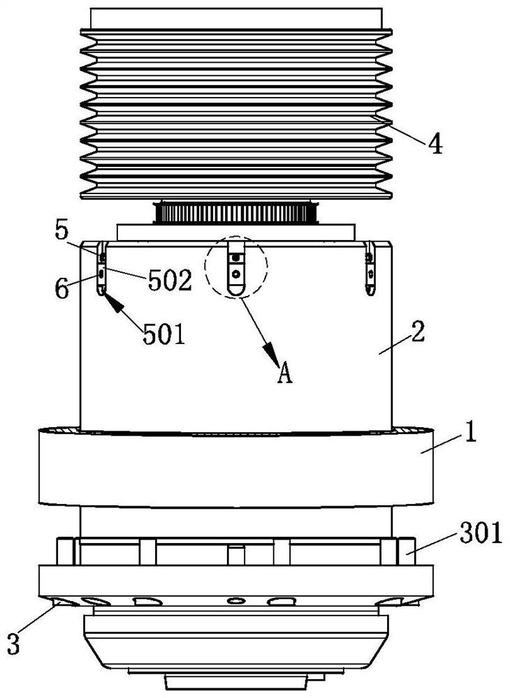
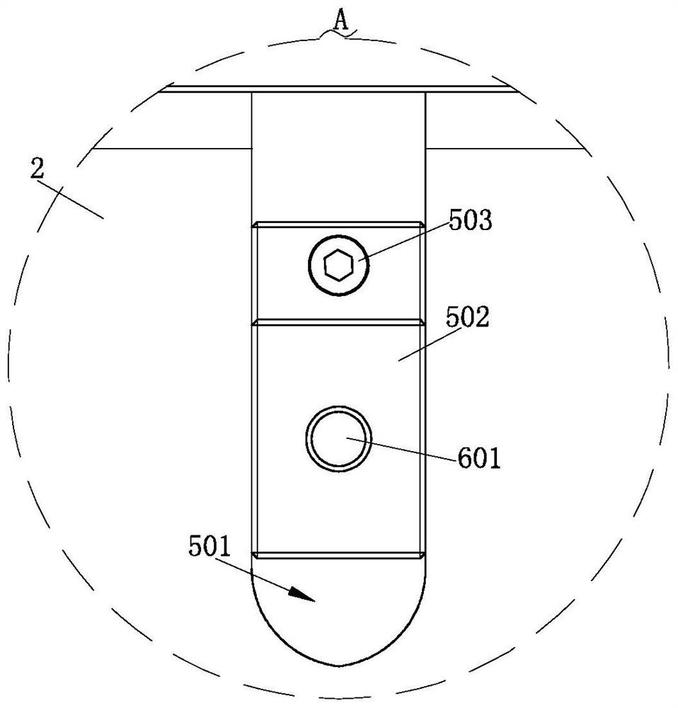
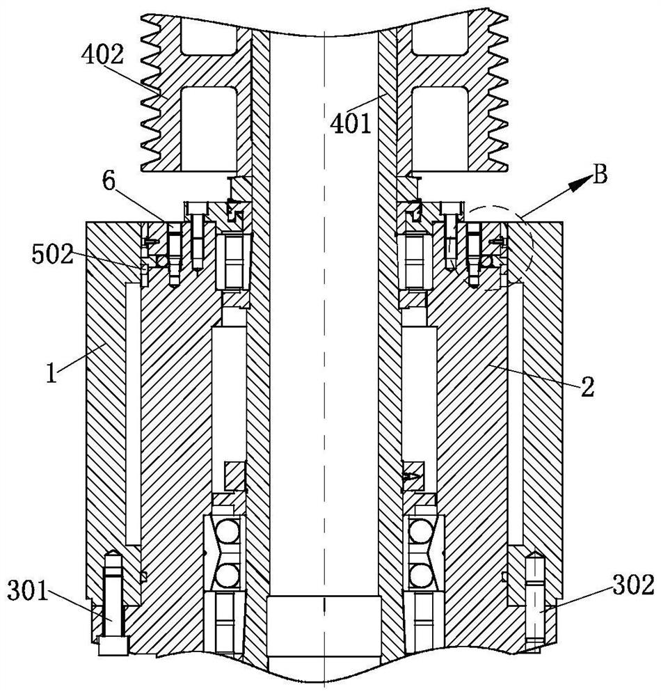
[0023] like Figure 1-Figure 4 As shown, the installation structure of a CNC machine tool spindle unit according to the present invention includes a spindle box 1, and the inside of the spindle box 1 is fixedly connected with a spindle sleeve 2 through a first fixing mechanism 3. A plurality of groups of connection mechanisms 5 are provided at equal distances on the outside, the top of the main shaft sleeve 2 is provided with a plurality of second fixing mechanisms 6 corresponding to the connection mechanisms 5, and the interior of the main shaft sleeve 2 is provided with a power mechanism 4;

[0024] The first fixing mechanism 3 includes a hexagon socket head screw 301 and a cylindrical pin 302, and the spindle sleeve 2 and the sp...


PUM


Abstract

The invention relates to the technical field of numerical control machine tool spindle installation, in particular to a numerical control machine tool spindle unit installation structure which comprises a spindle box, a spindle sleeve is fixedly connected to the interior of the spindle box through a first fixing mechanism, and multiple sets of connecting mechanisms are arranged on the outer side of the spindle sleeve at equal intervals. A plurality of second fixing mechanisms corresponding to the connecting mechanisms are arranged at the top of the main shaft sleeve, and a power mechanism is arranged in the main shaft sleeve; a plurality of second fixing mechanisms for reinforcing the spindle box are arranged on the spindle sleeve, so that the stress area is increased, the whole structure has stable retentivity, and more advantageously, when the power mechanism is mounted and operated, even if an application occasion driven by a belt pulley is encountered, the axial space between the belt pulley and the spindle sleeve can be utilized, so that the power mechanism can be stably fixed. And the main shaft sleeve can be quickly mounted and fixed without dismounting the belt pulley.

Description

technical field [0001] The invention relates to the technical field of spindle installation of CNC machine tools, in particular to an installation structure of a spindle unit of CNC machine tools. Background technique [0002] The machine tool spindle refers to the axis on the machine tool that drives the workpiece or tool to rotate. The spindle components are usually composed of spindles, bearings and transmission parts (gears or pulleys); the spindle components of CNC machine tools are developed into independent functional components, which are important guarantee links for the generalization, modularization and standardized production of modern machine tools; the main The function is to output power. [0003] However, when the current machine tool spindle and the spindle casing are connected, flanges are used for fixed support at the front and rear ends. It is difficult to ensure the shape and position tolerance of the box hole during the processing of the spindle box, a...

Claims


Application Information

Patent Timeline
IPC IPC(8): B23B19/02
CPCB23Q1/70Y02P70/10
Inventor 关晓勇余文斌胡明洪齐延男宫德海赵祖喜葛文伟杨笑东柳晓川
Owner 安徽新诺精工股份有限公司
Why Eureka
Try Eureka