Bat for table tennis

A table tennis racket and racket handle technology, applied in the field of table tennis rackets, can solve problems such as easy sweating, slipping of the racket handle, and difficulty in gripping

Inactive Publication Date: 2005-08-31
冯永逸
View PDF0 Cites 9 Cited by
  • Summary
  • Abstract
  • Description
  • Claims
  • Application Information

AI Technical Summary

Problems solved by technology

[0004] The second problem that cannot be ignored is: the wall surface of the racket handle of the existing table tennis racket is a wooden smooth elliptical column wall surface. The handle is slippery and difficult to hold, which affects the comfort of the hand and the accuracy of hitting the ball
[0005] The 3rd problem is: the hitting plate and the racket handle of the above-mentioned table tennis racket are actually rigidly connected to each other. on hand
Especially when hitting the ball at a high frequency, the resulting vibration may seriously affect the player's hitting accuracy and responsiveness

Method used


Image

  • Bat for table tennis
  • Bat for table tennis
  • Bat for table tennis

Examples


Embodiment 1

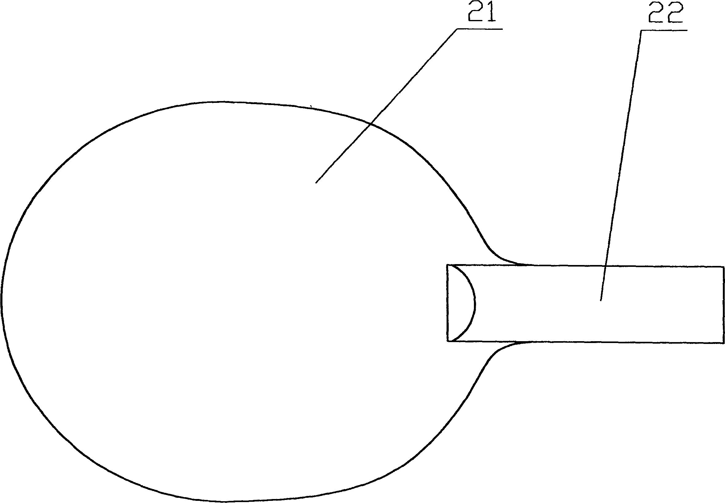
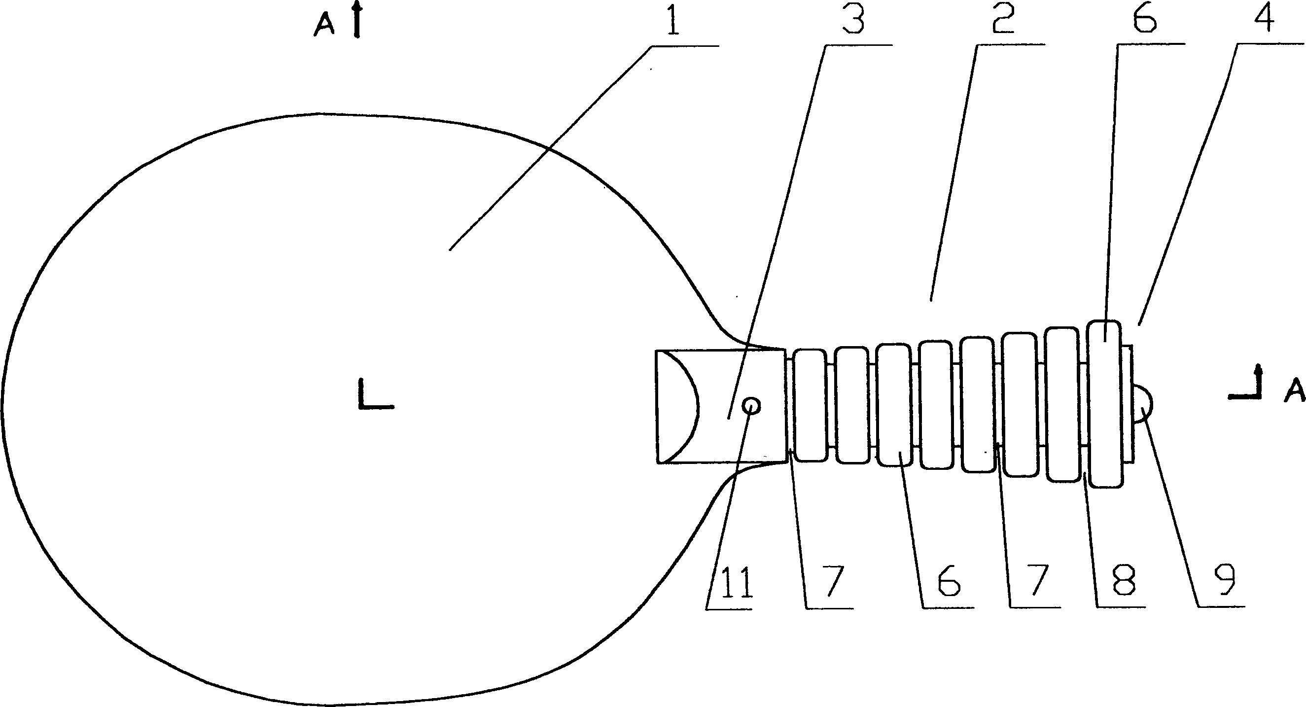
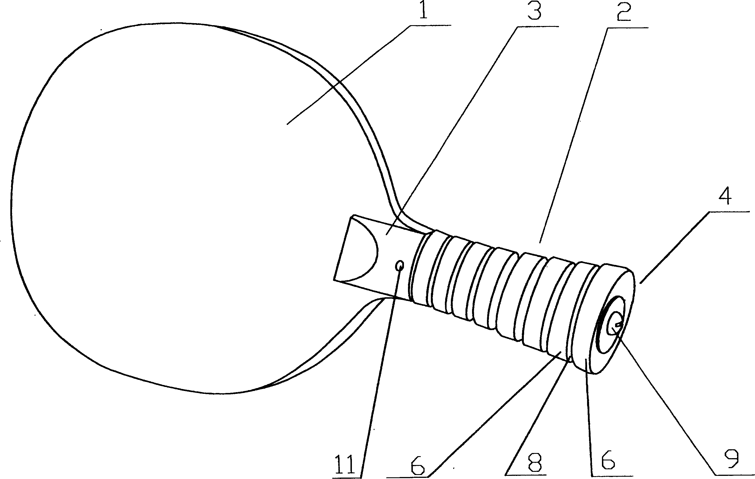
[0026] Embodiment 1: Reference Figure 1 to Figure 5 , a kind of table tennis racket, is made up of batting board 1 and racket handle 2, and racket handle 2 is divided into front section 3 and rear section 4 again, and rear section 4 is longer than front section 3, has accounted for the major part of racket handle, along the racket handle longitudinal In the axial direction, a carbon fiber tube 5 is inserted into the front section of the racket handle and fixed on the front section 3 of the racket handle by the positioning pin 11 on the front section 3 of the racket handle, and the carbon fiber tube 5 extends to the back section 4 of the racket handle. Tail end; the racket handle rear section 4 is made up of eight oval wooden rings 6 with a thickness of 6 mm that are worn on the pipe 5, and the arrangement of the rings is made from the inside to the outside to increase the radius, in order to improve the grip of the racket The comfort of the handle, the arc surface transition ...

Embodiment 2

[0028] Embodiment two: reference Figure 6 , its structure is basically the same as that of Embodiment 1, the difference is that the arrangement order of the rings 6 has been adjusted, and the rings forming the back section of the racket handle are arranged in a state of being large in the middle and small at both sides, forming a large middle and small at both ends racket handle.

Embodiment 3

[0029] Embodiment three: reference Figure 7 , its structure is basically the same as that of Embodiment 1, except that an annular gap is formed between the tube 5 and the center hole of the ring 6, and the annular gap is closed by an elastic sealing ring 10. The racket is purposely damped by means of elastic materials (such as the elastic sealing ring 10, the washer 7), so that the racket can advantageously damp the vibration transmitted to the hand when hitting the ball. This racquet remains stable and secure in the player's hands even at high stroke frequencies.

[0030] Of course, the embodiment of the present invention is not limited to the above examples. For example, the material of the ring 6 can be rubber; the tube 5 can also be made of the following bending-resistant materials, such as metal, plastic or carbon fiber fabric. ; Gasket 7 can also choose other materials.


PUM


Abstract

The present invention relates to a table tennis bat, including ball-driving plate and bat handle. Said bat handle can be divided into front part and rear part which can be separated, in which the front part is fixed and mounted on the ball-driving plate, along the longitudinal axis of bat handle a tube is fixed on the front part of bat handle, and is extended to tail end of rear part of the bat handle, the described rear part of the bat handle is formed from rings mounted on the tube, and on the tube wall of the described tube the screw thread is set, a fastening screw is connected with the tube screw thread from tail end of rear part of bat bandle, so that the ring can be tightly pressed and fixed on the front part of bat handle.

Description

[Technical field]: [0001] The invention relates to a table tennis racket. [Background technique]: [0002] Existing table tennis bat comprises hitting plate 21 and racket handle 22. The racket handle is generally formed by the extension of the batting plate and the handle cover that is non-detachably mounted on its extension, and the shape is mostly elliptical cylinder. The result is a highly stable and reliable table tennis racket. [0003] In the design of the racket handle, it is required that the shape and curve of the racket handle should conform to the physiological structure of the palm (especially important for horizontal racket users), so as to ensure that the hand feels comfortable when holding the racket handle. There is no guarantee that the racket handle of a pair of rackets can enable different people to obtain the best grip effect at the same time; in addition, each racket handle is fixedly designed with a grip angle that the designer thinks makes the hand f...

Claims


Application Information

Patent Timeline
Patent Type & Authority Patents(China)
IPC IPC(8): A63B59/42A63B60/12A63B102/08
Inventor 米高·史立德
Owner 冯永逸
Why Eureka
Try Eureka