Refrigerator

A technology for refrigerators and refrigerator bodies, which is applied to household refrigerators, coolers, lighting and heating equipment, etc., can solve problems such as increased costs, larger refrigerators, and smaller compartment capacity.

Inactive Publication Date: 2003-03-05
MITSUBISHI ELECTRIC CORP
View PDF0 Cites 9 Cited by
  • Summary
  • Abstract
  • Description
  • Claims
  • Application Information

AI Technical Summary

Problems solved by technology

[0004] However, in the conventional freezer described in the Publication No. 3-83793, in order to carry out effective deodorization, it is necessary to close the baffle of the main circulation air path. However, once the baffle is closed, the air resistance will decrease. If it becomes overwhelmingly large, the cold air will pass through the bypass air passage equipped with a deodorizing device, so the cold air will hardly enter the main circulation air passage, and the cooling of each chamber in the freezer will obviously be insufficient.
[0005] In addition, when the deodorization operation is performed while the compressor is stopped, there is also a problem that the temperature of each compartment of the freezer rises, so there is a problem that the improvement of the deodorization ability and the assurance of the cooling ability cannot be achieved at the same time.
Moreover, although the odor is used in the deodorization device and the odor is decomposed by the deodorization catalyst, the decomposition efficiency of the deodorization

Method used


Image

  • Refrigerator
  • Refrigerator
  • Refrigerator

Examples


Embodiment 1

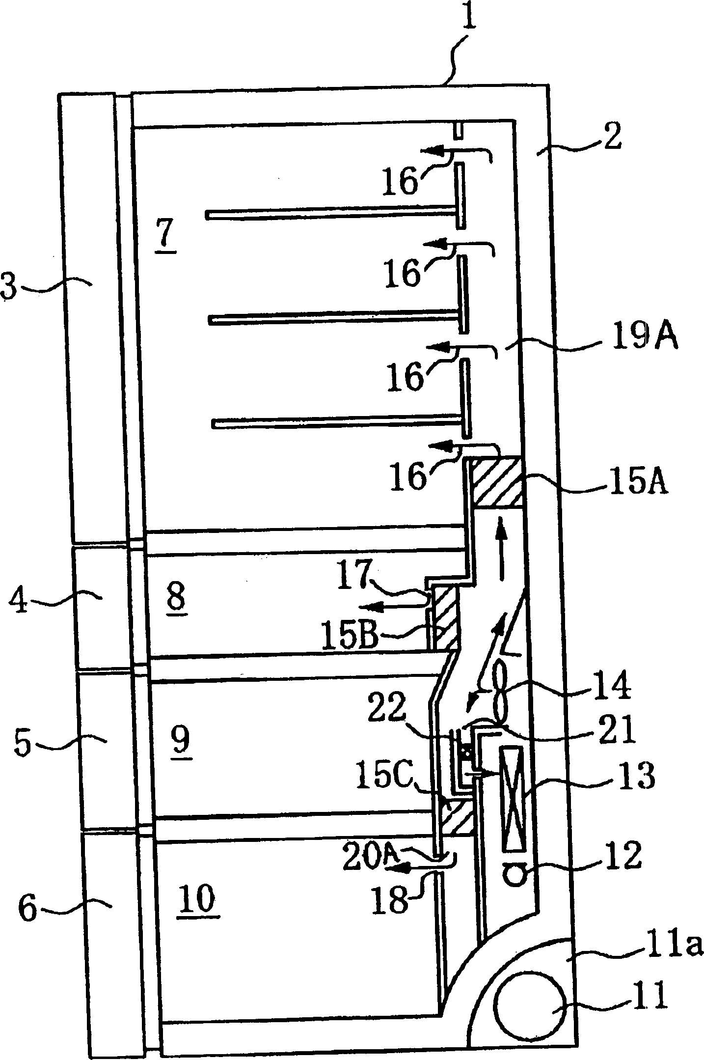
[0066] use Figure 1 to Figure 5 Embodiment 1 of the present invention will be described. figure 1 It is a side sectional view showing the refrigerator of Example 1 of this invention. 1 is the main body of the refrigerator, and 2 is the heat insulation box filled with heat insulation material. 7 is a refrigerating chamber installed on the upper part of the refrigerator body 1, 8 is a switching chamber installed under the refrigerating chamber 7, and can be switched over a wide range of temperature ranges from vegetables to frozen foods, and 9 is a switching room installed in the switching room 8. Bottom, a vegetable compartment for preserving vegetables and the like, 10 is a freezer compartment which is arranged under the vegetable compartment 9 and preserves frozen foods and the like.

[0067] 3 is an openable door for a refrigerator compartment installed in front of the refrigerator compartment 7, 4 is a door for a pull-out switch compartment installed in front of the swit...

Embodiment 2

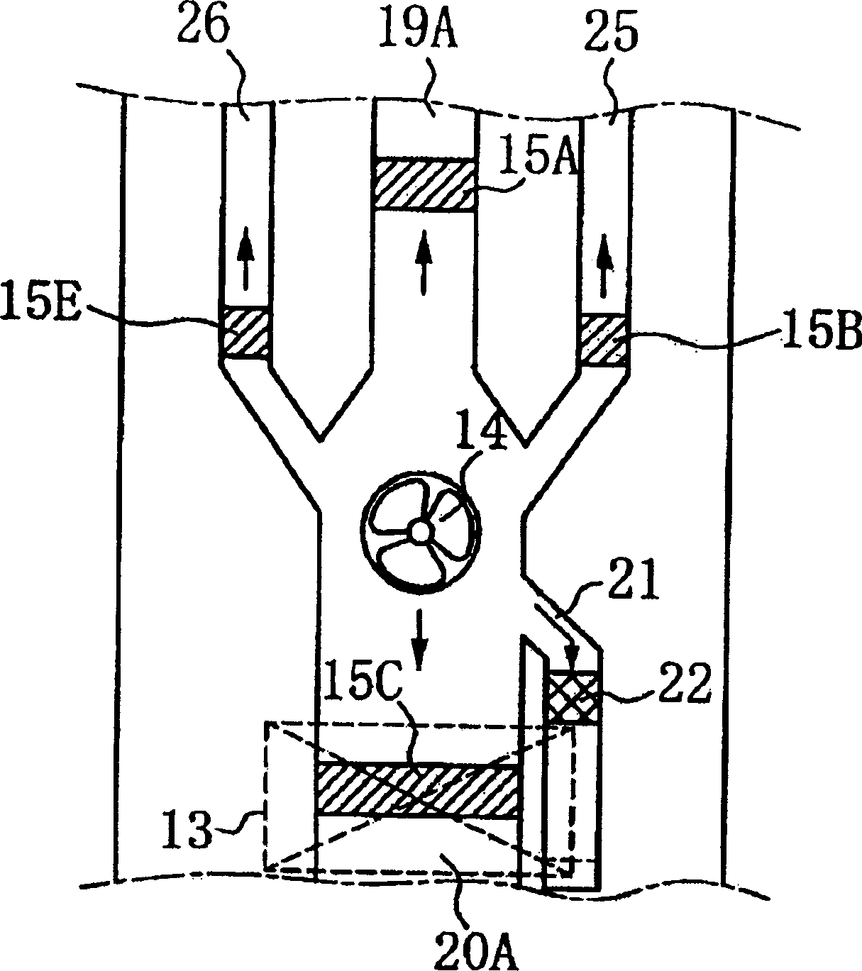
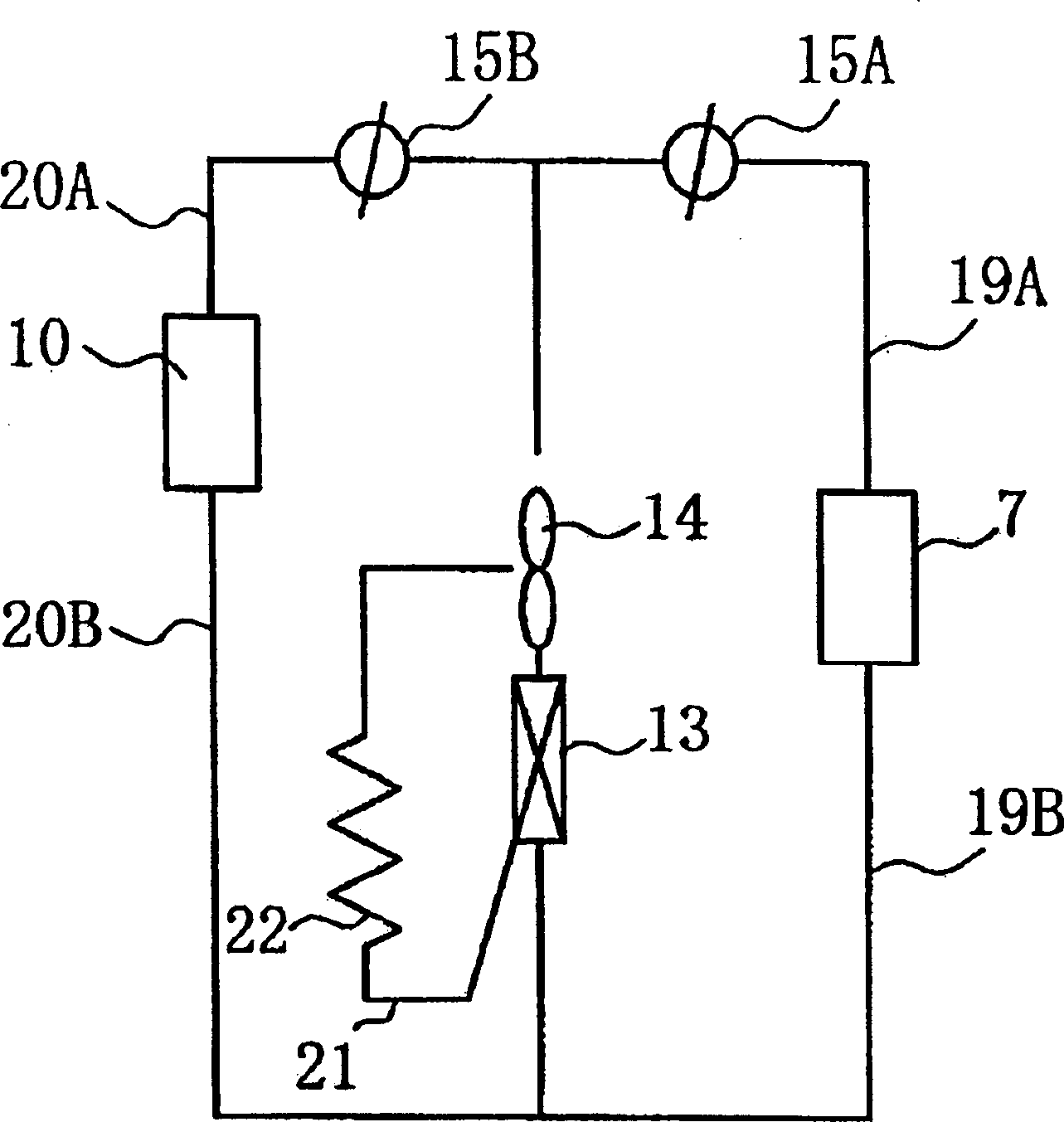
[0087] use Figure 7 ~ Figure 10 Embodiment 2 of the present invention will be described. Figure 7 It is a side sectional view of the refrigerator which shows an example of Embodiment 2 of this invention. Figure 8 It is a main part front view which shows a part of the air duct of the refrigerator of Example 2. Figure 9 It is a schematic wind path diagram which shows the schematic structure of the air path of the refrigerator of Example 2. exist Figure 7 , Figure 8 , Figure 9 In , the same parts as those in Embodiment 1 are marked with the same symbols and their descriptions are omitted. In this embodiment, a deodorizing baffle 15D for adjusting the flow rate passing through the bypass flow path 21 is provided in the bypass flow path 21 of the refrigerator main body 1 of the first embodiment.

[0088] exist Figure 7 , Figure 8 , Figure 9 Among them, 15D is a special deodorizing baffle installed in the bypass flow path 21. Since the deodorizing special baffle 1...

Embodiment 3

[0106]In this embodiment, all the cold air volume adjustment baffles provided in the refrigerator body 1 described in the second embodiment have the opening degree adjustment function. Fig. 11 is a control flowchart showing a control flow of the deodorizing device of the refrigerator according to the third embodiment. In the figure, S50 is a step of selecting a compartment for deodorizing operation, for example, a step of selecting a refrigerating room deodorizing operation when deodorizing operation of the refrigerating room 7 is selected. S51 is a deodorization operation switch activation step for activating the deodorization operation switch of the compartment (refrigerator compartment 7) selected in S50, and S52 is a defrosting operation determination step for determining whether the refrigerator is in defrosting operation.

[0107] S71 is a deodorizing operation refusal step for rejecting the deodorizing operation when it is judged that the defrosting operation is in prog...


PUM


Abstract

An odorless refrigerator with a deodorizing function free from insufficient refrigeration, which is provided with a deodorizing device operable with a stable deodorizing performance for a long time, simply structured, small-sized, and provided at a low cost. The refrigerator includes a draft air duct as a passage of refrigerated air blown off forcibly by an inside fan to the compartments, a damper in the draft air duct and opens/closes to allow/prevent the supply of refrigerated air to the compartments, a bypass channel in the draft air duct between the damper and a cooling device for returning refrigerated air from the cooling device to the cooling device, and a deodorizing device in the by-pass channel for deodorizing refrigerated air supplied to the compartments. The refrigerated air inside the draft air duct between the damper and the cooling device is forcibly blown off through the bypass channel by closing the damper.

Description

technical field [0001] The present invention relates to a refrigerator equipped with a deodorizing device. Background technique [0002] As an example of the known technology, there is a freezer with a deodorizing device described in Utility Application Publication No. 3-83793. The above-mentioned refrigerated refrigerator is provided with a bypass (by-pass) air path with a deodorizing device inside a part or all of the circulating air path in the refrigerator, and it is characterized in that: the air resistance is smaller than the above-mentioned bypass air path The circulation air path of the main circulation air path and the bypass air path in the refrigerator is in a shunt state. As for the deodorizing device, a combination of an odor generating device and a deodorizing catalyst is used. A baffle is provided in the main circulation air path, and the deodorizing effect is improved by closing the above-mentioned baffle. On the contrary, since the cold air can flow into ...

Claims


Application Information

Patent Timeline
IPC IPC(8): F25D17/08A61L9/00A61L9/16A61L9/20F25D17/04F25D17/06F25D23/00
CPCF25D2317/0415F25D2317/0682F25D17/042F25D2317/067F25D2317/0665F25D2400/04F25D17/065
Inventor 吉田淳二加藤睦平冈利枝大矢惠司荒木正雄
Owner MITSUBISHI ELECTRIC CORP
Why Eureka
Try Eureka