Axial positioning device of heat transfer pipe internal rotation cleaning element

A technology of axial positioning and heat transfer tubes, which is applied in the direction of cleaning heat transfer devices, rotating equipment cleaning, lighting and heating equipment, etc. It can solve the problems of difficult dirt cleaning resistance, reduced rotation torque of rotating cleaning elements, and low flow rate.

Inactive Publication Date: 2004-03-17
株洲工学院帅科机械清洗研究所
View PDF2 Cites 8 Cited by
  • Summary
  • Abstract
  • Description
  • Claims
  • Application Information

AI Technical Summary

Problems solved by technology

However, the nozzle fixing device of the rotating cleaning element has such a structural defect: there is no necessary guidance for the flow direction of the fluid inlet, and before the incoming liquid contacts the rotating cleaning element, swirling flow of different degrees will be generated at the inlet of the heat transfer tube , and according to the principle of least resistance, the swirling...

Method used


Image

  • Axial positioning device of heat transfer pipe internal rotation cleaning element
  • Axial positioning device of heat transfer pipe internal rotation cleaning element
  • Axial positioning device of heat transfer pipe internal rotation cleaning element

Examples


Embodiment Construction

[0012] The specific embodiment of patent of the present invention is illustrated below in conjunction with accompanying drawing:

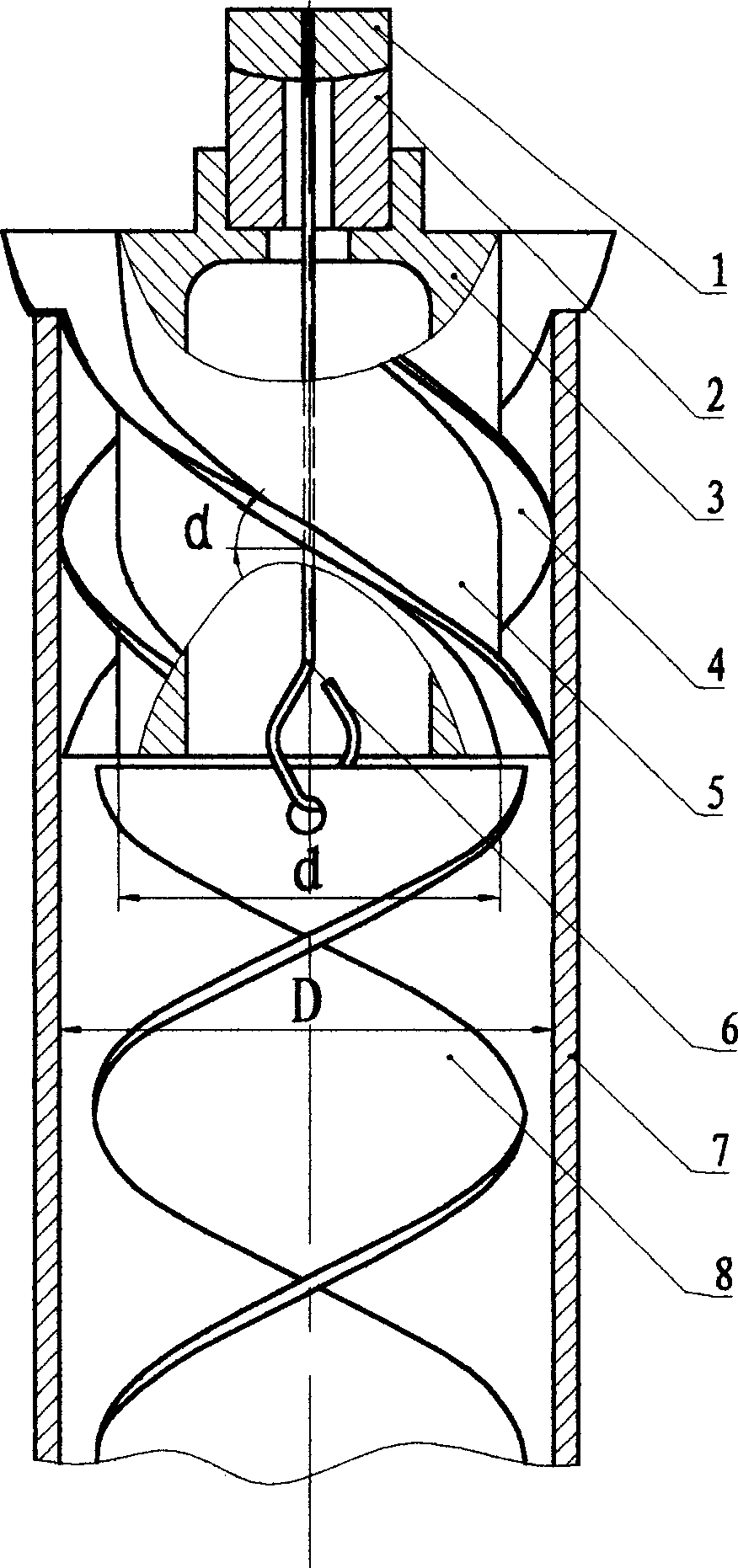
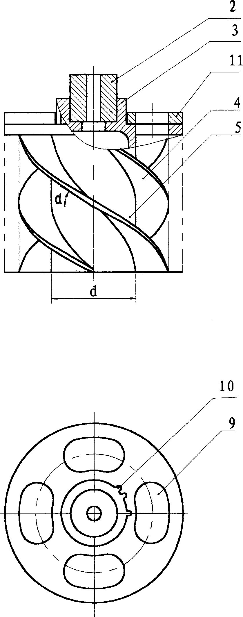
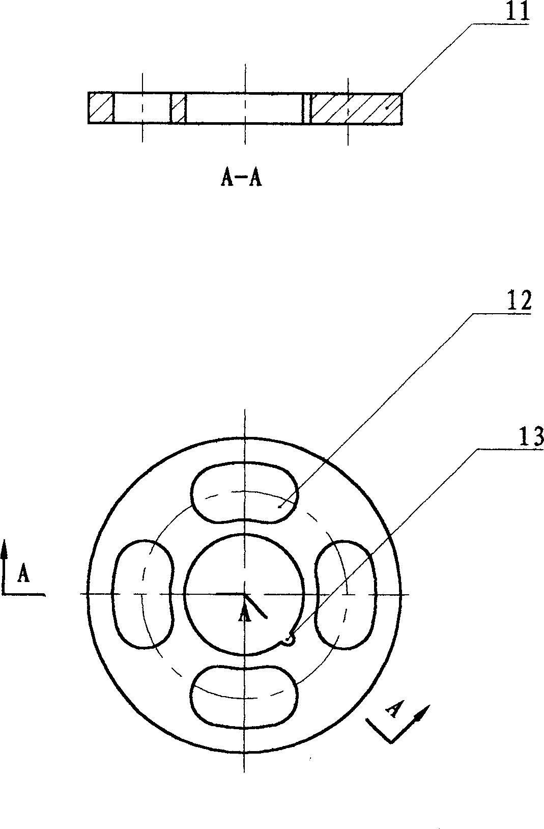
[0013] The axial positioning device of the rotary cleaning element in the heat transfer tube of the present invention is shown in figure 1 , the bearing seat 3 is installed at the inlet end of the heat transfer tube 7, and the bearing seat 3 is provided with a spiral deflector 4 and a wall-attached cylinder 5.

[0014] The helical direction of the deflector 4 is the same as that of the rotating cleaning element 8 (and opposite to that of the rotating cleaning element 8 ). The helix angle α of the deflector 4 is in the range of 20°∽60°. The preferred solution is that the lower the flow velocity in the pipe, the smaller the value of the helix angle, and the greater the flow velocity through the helical deflector 4 will be. The number of guide fins 4 is 1-6, and the preferred solution is that the larger the diameter of the heat transfer tube 7, the l...


PUM


Abstract

An axial positioning device of heat transfer pipe internal rotation cleaning element, wherein a helical flow channel is formed by the flow deflector arranged on the bearing seat, wall tube and thermal conducting pipe wall, the heat-transfer fluid flowing in the channel constitutes a rapid helical flow with long radius, pushing the rotating type cleaning element directly to produce a large kineticmoment, superposing with the self-torque of the cleaning element, thus increasing the original working torque by two times, and lowering the velocity in pipes needed by driving the cleaning element by over 60%.

Description

technical field [0001] The invention relates to an axial positioning device for a rotating cleaning element in a heat transfer tube. It is suitable for various shell and tube heat transfer equipment for on-line rotary cleaning, such as heat exchangers, condensers, evaporators, etc. Background technique [0002] US Patent No. 4174750 and Chinese Patent Document CN2214239Y both disclose a cleaning device in a heat transfer tube, which includes a heat transfer tube, a rotating cleaning element in the tube, and a fixing device for the rotating cleaning element at the liquid inlet end of the heat transfer tube. Driven by the heat transfer fluid in the tube, the rotating cleaning element rotates to scrape the dirt on the inner wall of the tube, and has the function of online, automatic and continuous cleaning and anti-scaling; due to the diversion effect of the rotating cleaning element, the liquid flows in a helical line, and the inside of the tube The disturbance of the fluid f...

Claims


Application Information

Patent Timeline
IPC IPC(8): F28G3/00
Inventor 蒋少青俞秀民俞天兰彭德其支校衡吴金香金俊杰
Owner 株洲工学院帅科机械清洗研究所
Why Eureka
Try Eureka