Antenna

An antenna and antenna element technology, applied to antennas, resonant antennas, antenna parts and other directions, can solve the problems of reduced antenna impedance, difficult impedance matching, inconvenient use, etc., to achieve stable antenna characteristics, reduced height, and antenna The effect of increasing impedance

Inactive Publication Date: 2004-08-11
PANASONIC CORP
View PDF1 Cites 1 Cited by
  • Summary
  • Abstract
  • Description
  • Claims
  • Application Information

AI Technical Summary

Problems solved by technology

[0011] Therefore, in order to reduce the size of the antenna, when the mechanical height h of the antenna element is reduced to a height shorter than 1 / 4 wavelength of the operating frequency, the impedance of the antenna is reduced, and it is difficult to perform impedance matching.
[0012] In addition, when the above-mentioned conventional antenna is installed on the rear bracket or the instrument panel in the vehicle, it is desirable to install the antenna elements 93 and 103 upward in order to improve the radio wave radiation efficiency of the antenna. However, when the antenna is positioned upward Set up, because the antenna elements 93, 103 occupy a large space in the height direction, so it is inconvenient to use in the vehicle

Method used


Image

  • Antenna
  • Antenna
  • Antenna

Examples


Embodiment approach 1

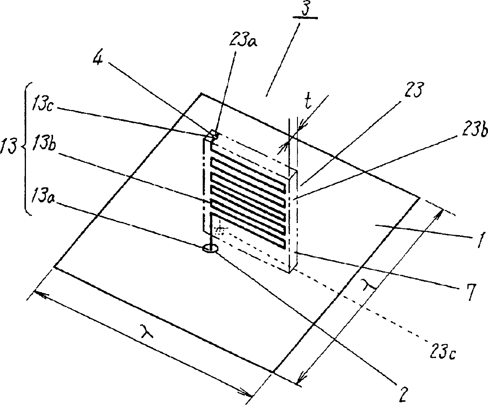
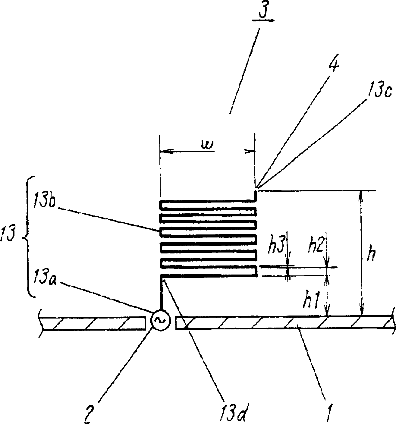
[0037] figure 1 It is a perspective view of the antenna according to Embodiment 1 of the present invention, figure 2 its side view. As shown in the figure, the antenna according to Embodiment 1 of the present invention has a flat conductor floor 1 made of copper or steel with vertical and horizontal dimensions of one wavelength or more, and a feeding point 2 located approximately in the center of the conductor floor 1 . In addition, one end 13 a of the first antenna element 13 made of a linear or plate-shaped copper material is connected to the feeding point 2 . The first antenna element 13 has a middle portion 13 b extending upward of the conductor floor 1 . The intermediate portion 13b is formed in a roughly U-shaped shape with multiple folds.

[0038] Similarly, one end 23 a of the second antenna element 23 made of copper or the like is connected to the other end 13 c of the first antenna element 13 at the connection point 4 . Like the first antenna element 13 , the s...

Embodiment approach 2

[0060] Figure 7 It is a side view of the antenna according to Embodiment 2 of the present invention. As shown in the figure, the antenna according to the second embodiment has a structure in which the first antenna element 13 and the second antenna element 23 are formed symmetrically with respect to the Z line on the same plane, such as a wire-shaped or plate-shaped copper material.

[0061] In the above configuration, when transmitting information, a high-frequency signal is supplied to the first antenna element 13 and the second antenna element 23 from the feeding point 2 at the center of the conductor floor 1 . Thus, the high-frequency current (i13) of the first antenna element 13 and the high-frequency current (i23) of the second antenna element 23 are excited in phase, and radio waves are emitted into the air. In addition, in the case of receiving information, reception is also possible by the reverse operation.

[0062] Thus, according to the second embodiment, by for...


PUM


Abstract

The antenna of the present invention comprises flat-plate ground plane 1, first antenna element 13 with one end 13a connected to feeding point 2 and intermediate portion 13b folded by a plurality of times, which is extended upward from the ground plane 1, and second antenna element 23 with one end 23a connected to the other end 13c of the first antenna element 13, with intermediate portion 23b formed in symmetrical relation to the first antenna element 13, and also, with the other end 23c connected to the ground plane 1. Thus, it is possible to obtain a small size antenna with the antenna element lowered in height.

Description

technical field [0001] The present invention relates to an antenna used in a mobile wireless device such as a vehicle. Background technique [0002] In recent years, linear monopole antennas or folded monopole antennas have generally been used as antennas for mobile wireless devices such as those used in vehicles. [0003] now, use Figure 11 Such a conventional antenna will be described. [0004] Figure 11 (a) is a side view of a conventional monopole antenna. A conventional monopole antenna is composed of a flat conductor plate 91 made of copper or the like, a feeding point 92 located in the center of the conductor plate 91 , and a linear antenna element 93 made of copper or the like. One end of the antenna element 93 is connected to the feed point 92 , while the other end extends vertically by a height h with respect to the conductor floor 91 in an open state. In this way, a monopole antenna is constructed. [0005] Figure 11 (b) is a side view of a conventional fol...

Claims


Application Information

Patent Timeline
Patent Type & Authority Applications(China)
IPC IPC(8): H01Q1/32H01Q1/38H01Q9/42
CPCH01Q1/3275H01Q9/42H01Q1/38
Inventor 稻继进石原广隆小川晃一前田友之
Owner PANASONIC CORP
Why Eureka
Try Eureka