Method and apparatus to generate tracking error signal, optical storage drive and lead-in control method

A technology of tracking error and signal generation, applied in optical recording/reproduction, instrumentation, information storage, etc., can solve problems such as failure and blocking data

Inactive Publication Date: 2004-09-01
SAMSUNG ELECTRONICS CO LTD
View PDF3 Cites 1 Cited by
  • Summary
  • Abstract
  • Description
  • Claims
  • Application Information

AI Technical Summary

Problems solved by technology

[0010] Since the DPP method is based on the PP method, the number of tracking error signals generated by the DPP method is so small that tracking cannot be performed satisfactorily when reproducing data from a CD having a pit depth of approximately λ / 4 or a narrow track pitch control, thereby causing import failures or preventing data from being reproduced from the CD

Method used


Image

  • Method and apparatus to generate tracking error signal, optical storage drive and lead-in control method
  • Method and apparatus to generate tracking error signal, optical storage drive and lead-in control method
  • Method and apparatus to generate tracking error signal, optical storage drive and lead-in control method

Examples


Embodiment Construction

[0034] Reference will now be made in detail to the preferred embodiments of the present invention, examples of which are illustrated in the accompanying drawings, wherein like reference numerals refer to like parts throughout. The embodiments are described below in order to explain the present invention by referring to the figures.

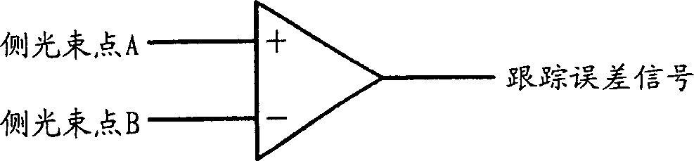
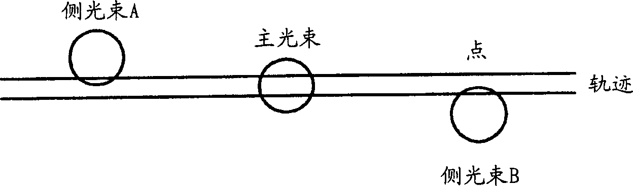
[0035] figure 1 is a diagram illustrating the structure of an apparatus for generating a tracking error signal by the 3-beam method. FIG. 2 is a diagram illustrating the principle of operation of the 3-beam method.

[0036] In the 3-beam method one main beam and two side beams are used. refer to Figure 2A , before or after the spot produced by the main beam, the points A and B produced by the respective side beams are formed on the trajectory, more specifically, the points A and B produced by the respective side beams deviate with respect to the point produced by the main beam half interval.

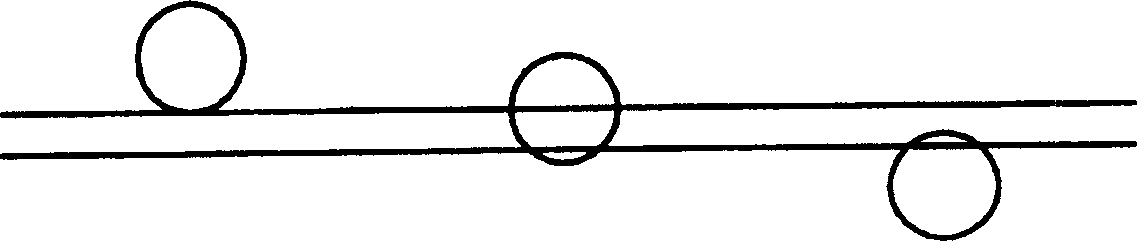
[0037] Figure 2B Illustrates the ideal spot cr...


PUM


Abstract

A method and apparatus to stably generate a tracking error signal even for a compact disc (CD) with a pit depth of about lambda / 4 or a narrow track pitch in an optical storage drive, an optical storage drive using the same, and a lead-in control method of the optical storage drive. The method includes detecting reflected laser beams using a photo detector; and generating a first tracking error signal based on optical signals received by the photo detector, using a differential phase detection (DPD) method and outputting the first tracking error signal as the tracking error signal.

Description

[0001] Cross References to Related Applications [0002] This application claims the benefit of Korean Patent Application No. 2002-75298 filed on November 29, 2002 and 2003-23060 filed on April 11, 2003 at the Korean Intellectual Property Office, the disclosures of which are incorporated herein by reference . technical field [0003] The present invention relates to a method and apparatus for generating a tracking error signal in an optical storage drive, and more particularly to a method and apparatus for stably generating a tracking error signal even with an optical disk (CD) having a pit depth of approximately λ / 4 or a narrow track pitch A device, an optical storage drive using the method and device, and a lead-in control method for the optical storage drive. technical background [0004] In general, optical discs to which data is written and read by lasers include CDs and digital versatile discs...

Claims


Application Information

Patent Timeline
Patent Type & Authority Applications(China)
IPC IPC(8): G11B7/09G11B7/00G11B7/085
CPCG11B7/0903G11B7/0906G11B7/0945G11B2007/0006
Inventor 朴昌洙李钟圭高城均
Owner SAMSUNG ELECTRONICS CO LTD
Why Eureka
Try Eureka