Method for mending excessive polishing of die cavity edge of shot-off forming master die cavity

A master mold and mold cavity technology, which is applied in the field of avoiding excessive polishing of the edge of the mold cavity of the injection molding master mold cavity, can solve the problem of lack of excessive polishing of the mold cavity edge, and achieve the effect of avoiding burrs

Inactive Publication Date: 2005-04-06
BENQ CORP
View PDF0 Cites 13 Cited by
  • Summary
  • Abstract
  • Description
  • Claims
  • Application Information

AI Technical Summary

Problems solved by technology

Therefore, there is a lack of methods for avoiding the formation of burrs in the known technology to improve the excessive polishing of the mold cavity edge of the female mold cavity

Method used


Image

  • Method for mending excessive polishing of die cavity edge of shot-off forming master die cavity
  • Method for mending excessive polishing of die cavity edge of shot-off forming master die cavity
  • Method for mending excessive polishing of die cavity edge of shot-off forming master die cavity

Examples


Embodiment Construction

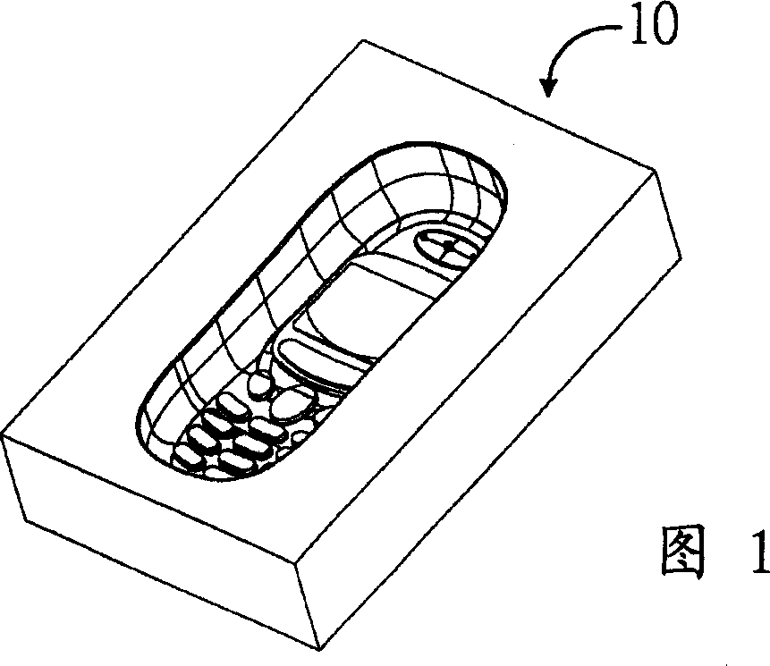
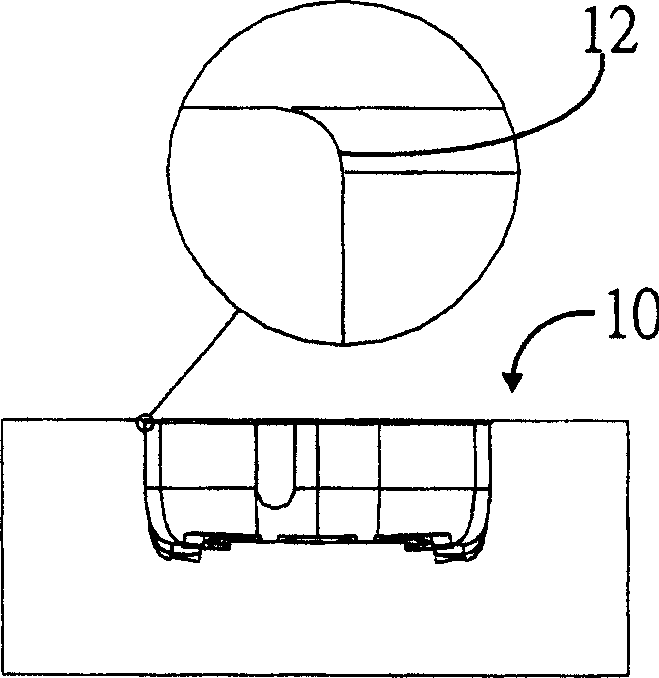
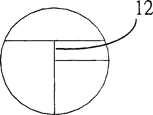
[0034] The invention provides a method for manufacturing a jnjection mold cavity for injection molding, which can avoid an excessive polishing phenomenon on the edge of the cavity of the jnjection mold cavity. The method of the present invention utilizes an auxiliary fixture to protect the cavity of the mother mold during polishing. The auxiliary jig has a central hollow substantially conforming to the shape of the edge of the cavity of the rough mold. The so-called over-polishing phenomenon refers to the unexpected deformation (deform) formed during the polishing of the edge of the cavity of the female mold cavity or the edge of the central hole of the auxiliary fixture.

[0035] refer to Figure 4 , Figure 4 It is a schematic diagram of the mold cavity blank 50 of the female mold cavity of the present invention. The blank 50 of the female mold cavity used in the present invention has a mold cavity 52 and three positioning holes 54 (setting holes) and four screw holes 56 ...


PUM


Abstract

The invention relates to a manufacturing method of the master die cavity which is used to shoot up forming die. It can prevent the edge of the die cavity from over buffing. An auxiliary gripper is utilized to protect the master die cavity while buffing. The auxiliary gripper has a center hole, and its shape is corresponded to the edge of the die cavity. The manufacturing method includes the following steps that the corresponding fixed structure and location structure are forming at a die cavity rough blank and auxiliary gripper. The auxiliary gripper is located at the die cavity rough blank by the location structure. And the relative relation of the auxiliary gripper and the die cavity rough blank is kept in constant by the fixed structure. The composite unit formed by the auxiliary gripper and the die cavity rough blank is practiced electro discharge machining programming by an electrode. The required master die cavity is made in the concave center of the die cavity. The composite unit is practiced buffing programming. Then the fixed structure is loosened. The auxiliary gripper is moved away from the master die cavity, so that the intact and satisfactory master die cavity is gained to practice the subsequent programming to shoot up the forming die.

Description

technical field [0001] The invention relates to a method for avoiding excessive polishing of the mold cavity edge of an injection molding female mold cavity. Background technique [0002] Many plastic injection molded products, such as casings of mobile phones, digital cameras, etc., need to be produced using master mold cavities. A master mold cavity is often used to produce more than ten thousand pieces of plastic injection molded parts (jnjected parts), therefore, the quality of the master mold cavity affects the quality of the entire batch of plastic injection molded parts. The master cavity must undergo a polishing procedure to make the surface inside the cavity of the master cavity smoother for injection molding. However, during polishing, the edge of the mold cavity of the female mold cavity is often slightly deformed due to excessive polishing. [0003] See Figure 1, Figure 2A and Figure 2B , FIG. 1 is a schematic diagram of a known female mold cavity 10 . Figu...

Claims


Application Information

Patent Timeline
Patent Type & Authority Applications(China)
IPC IPC(8): B23P15/24B24B1/00
Inventor 李文魁潘隆智
Owner BENQ CORP
Why Eureka
Try Eureka