Batch machining treatment method for clutch accessory

A processing method and clutch technology, applied in metal processing equipment, manufacturing tools, grinding workpiece supports, etc., can solve the problems of excessive polishing of the surface of the clutch pressure plate, increase the workload of employees, and affect the polishing quality, etc., to achieve rapid disassembly, The effect of increasing workload and improving production efficiency

Active Publication Date: 2020-09-11
苏州勤堡精密机械有限公司
View PDF9 Cites 0 Cited by
  • Summary
  • Abstract
  • Description
  • Claims
  • Application Information

AI Technical Summary

Problems solved by technology

[0003] The existing clutch pressure plate often has the following problems when performing polishing operations: a: When the existing clutch pressure plate is performing polishing operations, it often shakes due to the instability of the clutch pressure plate during polishing, resulting in excessive polishing of the clutch pressure plate surface Phenomenon occurs, which affects the polishing quality; b: When the existing clutch pressure plate is being polished, the wear of a single polishing sheet is often serious. In order to meet the polishing conditions, the entire group of polishing sheets is often replaced, which is a great waste of cost , and increased the workload of employees

Method used


Image

  • Batch machining treatment method for clutch accessory
  • Batch machining treatment method for clutch accessory
  • Batch machining treatment method for clutch accessory

Examples


Embodiment Construction

[0031] The embodiments of the present invention will be described in detail below with reference to the accompanying drawings, but the present invention can be implemented in many different ways defined and covered by the claims.

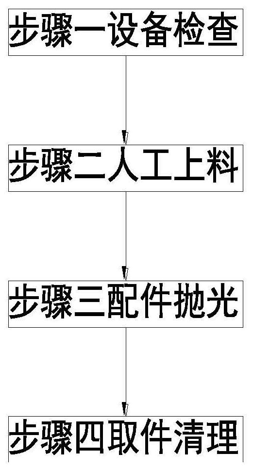
[0032] Such as Figure 1 to Figure 9 As shown, a batch processing method for clutch accessories mainly includes the following steps:

[0033] Step 1: Equipment inspection: Check the operation of the equipment before using the clutch accessories polishing device to polish the clutch accessories;

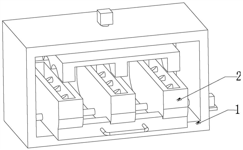
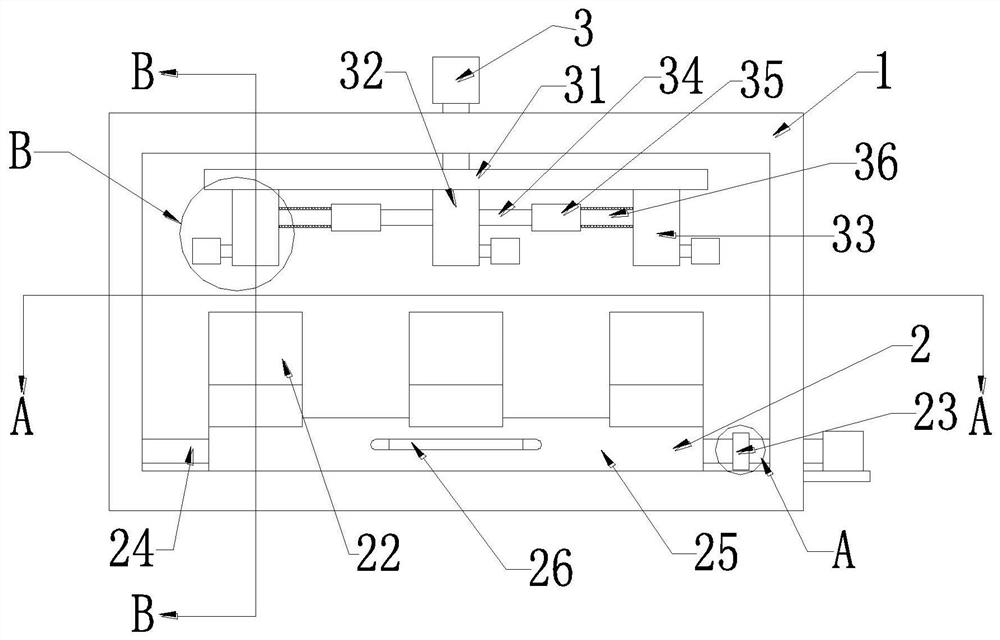
[0034] Step 2: Manual loading: Manually place the clutch pressure plate that needs to be polished on the charging block 22, and the charging block 22 works to fix the clutch pressure plate, thereby completing the manual loading operation;

[0035]Step 3: Accessories polishing: After completing the manual loading operation in Step 2, the No. 1 motor works, and drives the rotating shaft 24 to rotate through the docking block 23, thereby driving the clutch pr...


PUM


Abstract

The invention relates to a batch machining treatment method for a clutch accessory. The batch machining treatment method mainly comprises the following steps of equipment inspection, manual feeding, accessory polishing and accessory clearing; and a polishing device for the clutch accessory comprises a mounting frame, a fixing kit and a polishing kit, wherein the fixing kit and the polishing kit are sequentially arranged inside the mounting frame from bottom to top. The batch machining treatment method for the clutch accessory can solve the following problems existing when an existing clutch accessory is subjected to polishing operation that a, when the existing clutch pressure plate is subjected to polishing operation, the clutch pressure plate usually shakes due to unstable fixation of the clutch pressure plate during polishing, so that the phenomenon that the surface of the clutch pressure plate is excessively polished occurs, and the polishing quality is influenced; and b, when theexisting clutch pressure plate is subjected to polishing operation, the abrasion of a single polishing sheet is usually serious, in order to meet the polishing condition, the whole set of polishing sheets is usually replaced, the cost is greatly wasted, and the workload of staff is increased.

Description

technical field [0001] The invention relates to the technical field of clutch parts production, in particular to a batch processing method for clutch parts. Background technique [0002] The clutch is located in the flywheel housing between the engine and the gearbox, and the clutch assembly is fixed on the rear plane of the flywheel with screws. The output shaft of the clutch is the input shaft of the gearbox. The clutch is the engine power of the car or other power machinery. The device transmitted to the axle in the form of a switch. During the use of the clutch, some accessories are often required to cooperate with the clutch to work in the car, such as the clutch pressure plate. In order to meet the needs of use, the surface of the clutch pressure plate is often polished. , the existing clutch pressure plate needs to carry out steps such as equipment inspection, manual feeding, accessories polishing and accessories cleaning when polishing. [0003] The existing clutch ...

Claims


Application Information

Patent Timeline
Patent Type & Authority Applications(China)
IPC IPC(8): B24B1/00B24B29/02B24B41/02B24B41/06B24B47/12B24B47/14B24B41/04B24B41/00
CPCB24B1/00B24B29/02B24B41/02B24B41/06B24B47/12B24B47/14B24B41/04B24B41/005
Inventor 方志兰
Owner 苏州勤堡精密机械有限公司
Why Eureka
Try Eureka