Permanent magnet punching machine

A technology of permanent magnets and punching machines, which is applied in the direction of punching machines, presses, manufacturing tools, etc., can solve the problems of complex control systems, large input power and large power consumption of electromagnetic punching machines, and achieve the reduction of overall machine volume and system Power consumption, the effect of low power consumption of the whole machine

Inactive Publication Date: 2006-01-04
平南县科学技术情报研究所
View PDF0 Cites 19 Cited by
  • Summary
  • Abstract
  • Description
  • Claims
  • Application Information

AI Technical Summary

Problems solved by technology

[0008] The purpose of the present invention is to provide a permanent magnet punch press, which solves the technical problems of the known electromagnetic punch press, such as large input power, large power consumption, and complicated control system.

Method used


Image

  • Permanent magnet punching machine
  • Permanent magnet punching machine
  • Permanent magnet punching machine

Examples


Embodiment Construction

[0035] The technical solution of the present invention will be described in detail below with reference to the accompanying drawings.

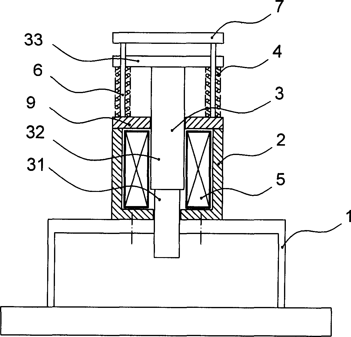
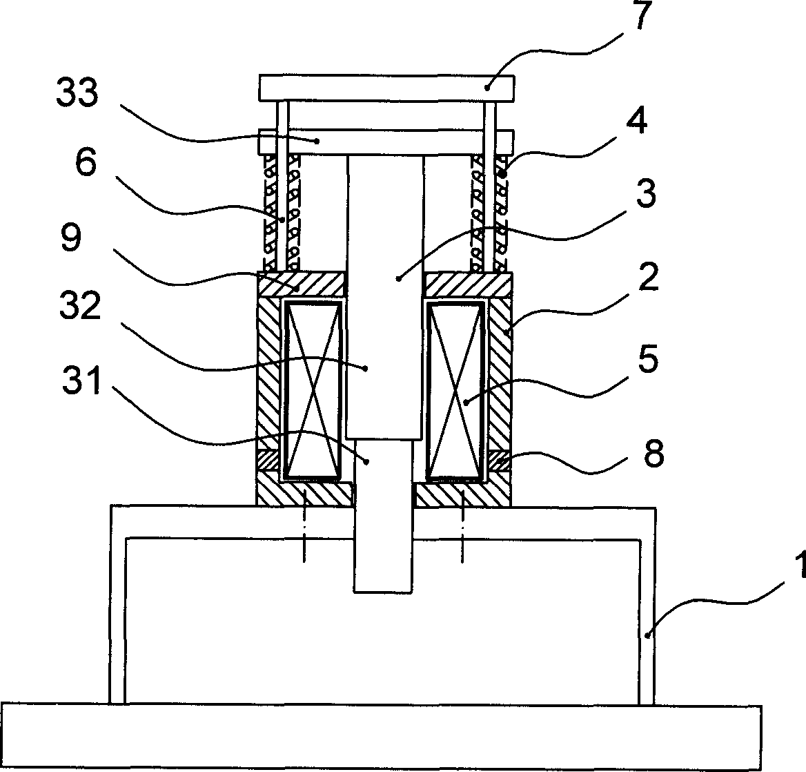
[0036] figure 2 It is a schematic diagram of the structure of the permanent magnet punch of the present invention. Such as figure 2 As shown, the permanent magnet punch of the present invention includes a frame 1, a yoke 2, an end plate 9, a guide column 6 and a limit plate 7, which are sequentially connected, and also includes a punch spindle 3 penetrating through the yoke 2, and the punch spindle 3 is composed of a punch 31, an armature 32 and a guide plate 33 connected in sequence. The end plate 9, the bottom surface of the yoke 2 and the support 1 are all provided with through holes for the punch spindle 3 to pass through. The electromagnetic coil 5 that generates the electromagnetic field is arranged in the circular space between the inner wall of the yoke 2 and the punch spindle 3. The electromagnetic field generated by it generates an elec...


PUM


Abstract

The permanent magnetic punch includes a yoke iron, a punching head reciprocating up and down inside the yoke iron, and an armature connected to the punching head. The present invention features that the permanent magnetic punch includes also a magnetic driving mechanism to make the yoke iron and the armature to constitute one magnetic loop, and the magnetic driving mechanism is provided with electromagnetic mechanism to apply electromagnetic drive force to the armature and permanent magnet to apply permanent magnetic attraction force to the armature. The present invention is superior to available electromagnetic punch, which has great power consumption and complicated control system.

Description

Technical field [0001] The invention relates to a punching machine, in particular to a permanent magnet punching machine adopting a permanent magnet electromagnetic mechanism. Background technique [0002] With the development of the electronics industry and the advent of the information age, traditional mechanical presses have been replaced by oil-free, clean, and high-frequency electromagnetic presses. figure 1 It is a schematic diagram of the structure of a known electromagnetic punch. Such as figure 1 As shown, the electromagnetic mechanism is arranged on the frame, and the electromagnetic mechanism is composed of a yoke, an electromagnetic coil, a coil former and an armature with a non-magnetic punch. The armature is connected with the guide sleeve plate, and the guide sleeve plate can move up and down in the guide post. Its working principle is: when current is applied to the electromagnetic coil, the armature moves downward by the electromagnetic driving force, and at th...

Claims


Application Information

Patent Timeline
Patent Type & Authority Applications(China)
IPC IPC(8): B30B1/42
Inventor 李国坤李珂程玉林崔国平姬全胜
Owner 平南县科学技术情报研究所
Why Eureka
Try Eureka