Speaker module

a speaker module and speaker technology, applied in the field of electroacoustic products, can solve the problems of the performance defects of the module, and achieve the effects of improving the sensitivity of the speaker module at the high frequency band, reducing the acoustic performance of the module, and prolonging the propagation distance of sound waves

Active Publication Date: 2018-12-18
GOERTEK INC
View PDF13 Cites 2 Cited by
  • Summary
  • Abstract
  • Description
  • Claims
  • Application Information

AI Technical Summary

Benefits of technology

[0004]A technical problem to be solved by the present invention is to provide a speaker module which can effectively improve the deep valley phenomenon of the sensitivity at high frequencies, and can improve the acoustic performance of the speaker module.
[0017]The sound hole of the speaker module of the present invention is located at the lateral side of the speaker unit, the speaker unit divides the whole inner cavity of the module into the front acoustic cavity and the rear acoustic cavity, the front acoustic cavity is in communication with the sound hole, and the sound-absorbing cotton is arranged in the front acoustic cavity. When the distance between a sound source and a reflecting surface of the front acoustic cavity (i.e., the inner wall of the housing which surrounds the front acoustic cavity) is equal to a quarter of the wavelength of one frequency in the high frequency band, a standing wave may be formed in the front acoustic cavity after the transmitting waves and the reflecting waves superimposed with each other. The present invention provides the sound-absorbing cotton in the front acoustic cavity, i.e., the sound-absorbing cotton is provided between the speaker unit and the reflecting surface of the front acoustic cavity, which equivalently lengthens the propagation distance of the sound waves in the front acoustic cavity, so that the position where the standing wave is generated is avoided, and the sensitivity of the speaker module at the high frequency band is effectively improved. Further, the sensitivity curve of the present invention is shown in FIG. 10, wherein the sensitivity curve at the frequency point in the area within the dotted line has obvious improvement compared to the sensitivity curve at the same frequency point in FIG. 9, thus the acoustic performance of the product is improved. The present invention effectively improves the performance of the sensitivity of the module at high frequencies without modifying the structure of the front acoustic cavity, which not only improves the acoustic performance of the module, but also simplifies the structure of the front acoustic cavity of the module.

Problems solved by technology

As shown in the area of the dotted line in FIG. 9, the sensitivity curve of the speaker module generates a deep valley in the vicinity of the frequency of 10000 Hz, which seriously impacts on the sensitivity of the speaker module in this frequency band, reduces the acoustic performance of the module, and results in performance defects of the module.

Method used


Image

  • Speaker module
  • Speaker module
  • Speaker module

Examples


embodiment 1

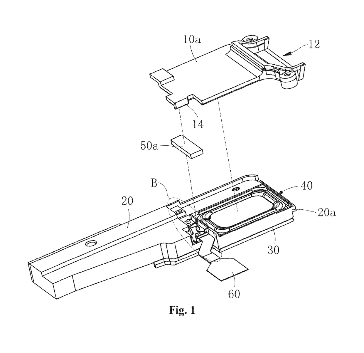
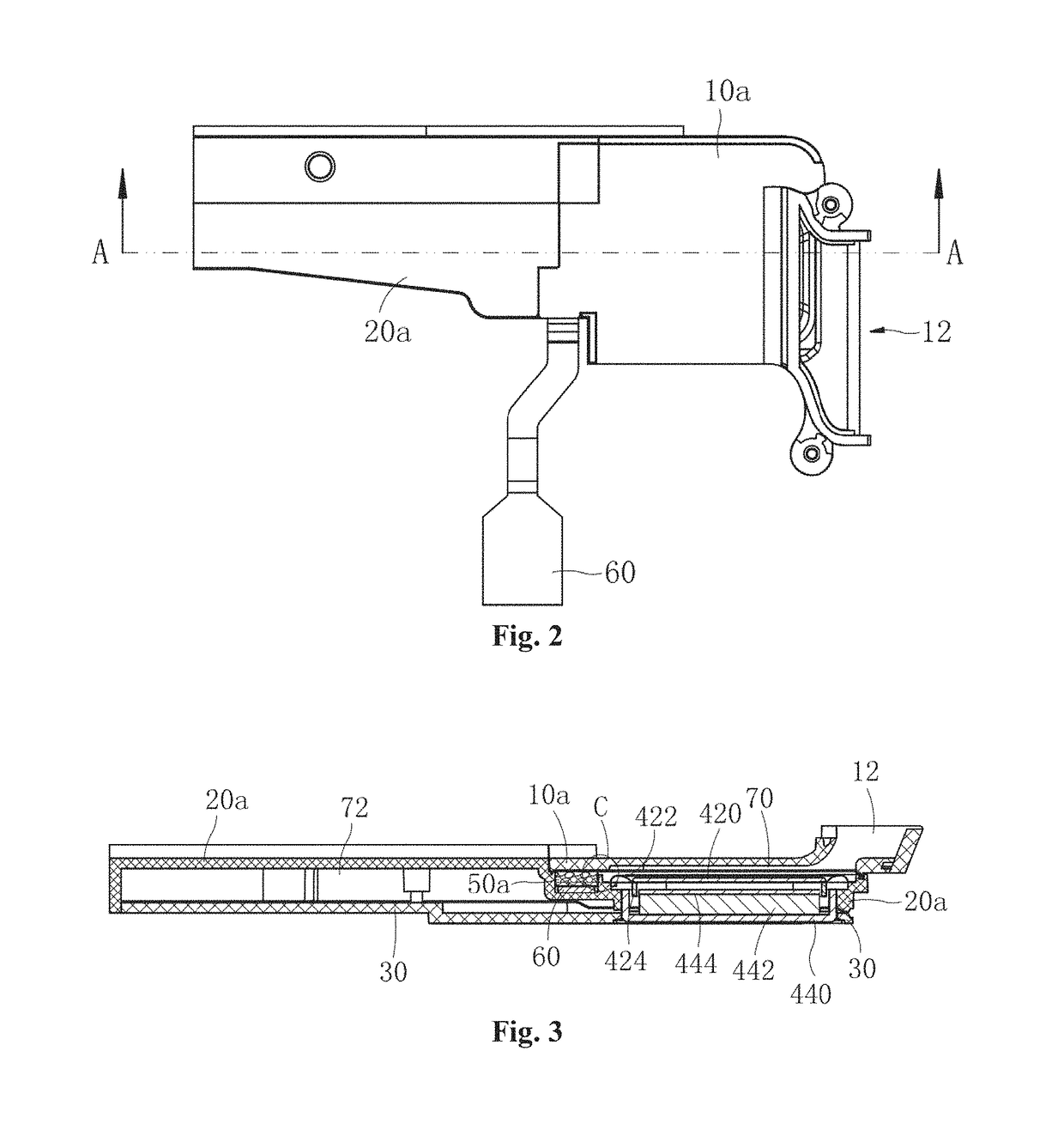
[0031]As shown in FIG. 1 and FIG. 2, a speaker module comprises a module housing, which comprises a first housing 10a, a second housing 20a and a third housing 30 successively combined together, and the space defined by the first housing 10a, the second housing 20a and third housing 30 accommodates a speaker unit 40 having a rectangular structure. A sound hole 12 of the module is located at one side of the speaker unit 40, and the sound hole 12 is located on the first housing 10a.

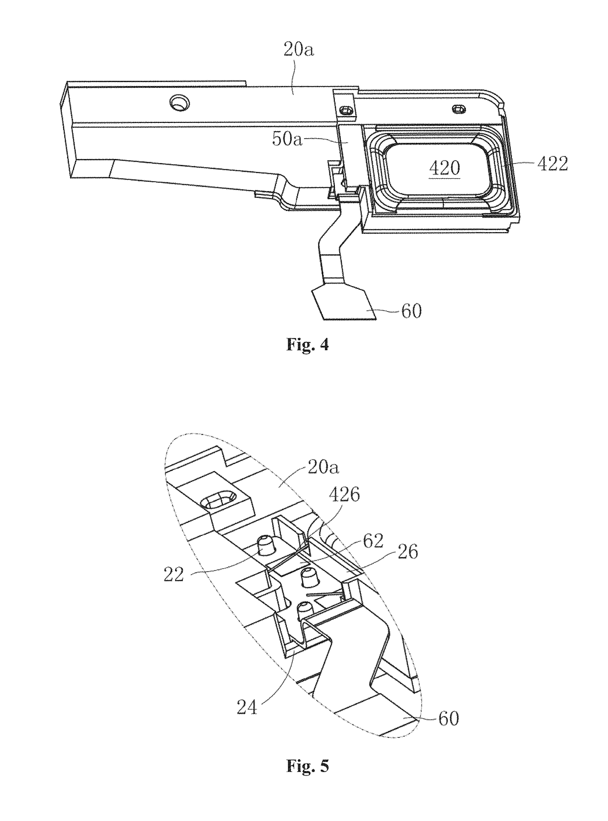
[0032]As shown in FIG. 3, the speaker unit 40 comprises a vibration system and a magnetic circuit system. The vibration system comprises a vibrating diaphragm 422, and the edge part of the vibrating diaphragm 422 is fixed on the second housing 20a; one side of the vibrating diaphragm 422 closer to the first housing 10a is provided with a dome 420 fixed on the central position of the vibrating diaphragm 422, and the other side of the vibrating diaphragm 422 is provided with a voice coil 424 fixed thereon. T...

embodiment 2

[0038]As shown in FIG. 7, embodiment 2 is basically identical to embodiment 1, and their difference lies in:

[0039]The sound-absorbing cotton 50b is fixed on the first housing 10b, instead of being fixed on the second housing 20b. The sound-absorbing cotton 50b is fixed on the inner side of the first housing 10b at the sound hole 12. The sound-absorbing cotton 50b is used for preventing the sound wave reflected onto the inner wall of the first housing 10b from generating a standing wave, and has a technical effect identical to that of embodiment 1.

embodiment 3

[0040]As shown in FIG. 8, embodiment 3 is basically identical to embodiment 1, and their difference lies in:

[0041]The sound-absorbing cotton 50c is fixed on the first housing 10c, instead of being fixed on the second housing 20c. The sound-absorbing cotton 50c is fixed over the speaker unit, i.e., on the inner wall of the first housing 10c opposite to the sound emitting surface of the speaker unit, and a space for the vibrating diaphragm to vibrate is formed between the sound-absorbing cotton 50c and the speaker unit. The sound-absorbing cotton 50c is used for preventing the sound wave reflected onto the inner wall of the first housing 10c from generating a standing wave, and has a technical effect identical to that of embodiment 1.


PUM


Abstract

A speaker module comprising a module housing is disclosed. A speaker unit is accommodated within the module housing. A sound hole of the module is located at a side of the speaker unit. The speaker unit divides a cavity of the entire module into two cavities, namely a front acoustic cavity and a rear acoustic cavity. The front acoustic cavity is in communication with the sound hole. A sound-absorbing cotton is provided in the front acoustic cavity. The sound-absorbing cotton is fixed on the module housing, and is arranged to avoid a vibration space of a diaphragm of the speaker unit. The present invention effectively improves the performance of a sensitivity curve of the module at high frequencies without modifying the structure of the front acoustic cavity, thus not only increasing the acoustic performance of the module, but also simplifying the structure of the front acoustic cavity of the module.

Description

TECHNICAL FIELD[0001]The present invention relates to the technical field of electro-acoustic products, particularly to a speaker module emitting sound at a lateral side.BACKGROUND ART[0002]The speaker module is an important acoustic component of a portable electronic apparatus, and is used for implementing conversion between an electronic signal and a sound signal, and the speaker module is an energy conversion device.[0003]Along with the continuous development of the portable electronic apparatus towards a light, thin and small architecture, the speaker module, as the acoustic component of a portable electronic apparatus, also develops towards the light, thin and small architecture, and therefore, the technicians design more and more speaker modules to have a structure emitting sound at a lateral side of the front cavity. This kind of structure results in that most of sound waves emitted by a speaker unit cannot be directly spread out, but only can be spread out from the sound hol...

Claims


Application Information

Patent Timeline
Patent Type & Authority Patents(United States)
IPC IPC(8): H04R1/28H04R9/06H04R1/06H04R1/02H04R9/02
CPCH04R1/288H04R1/025H04R1/06H04R9/06H04R9/025H04R2499/11H04R1/2865
Inventor SHAO, SHUAIXU, CHAOSHAN, LIANWEN
Owner GOERTEK INC
Why Eureka
Try Eureka