Vehicle

a technology for vehicles and headlamps, applied in the field of vehicles, can solve the problems of difficult irradiation of distant regions by head lamps, discomfort of rider,

Active Publication Date: 2019-06-04
KAWASAKI MOTORS LTD
View PDF14 Cites 0 Cited by
  • Summary
  • Abstract
  • Description
  • Claims
  • Application Information

AI Technical Summary

Benefits of technology

[0007]In accordance with this configuration, when the vehicle body is banked to the predetermined preceding bank state with a bank angle smaller than that of the predetermined set bank state, the auxiliary lamp is lighted in the preceding lighting state, and can irradiate the auxiliary lamp irradiation region, in the traveling direction of the vehicle body, before the auxiliary lamp reaches the set lighting state. This allows the rider to well see a region to which the vehicle turns, in the front region in the traveling direction while the vehicle is turning. Since the auxiliary lamp is lighted in the preceding lighting state, before the auxiliary lamp reaches the set lighting state, when the vehicle is banked to the first side in the vehicle width direction, a change in the brightness of the light can be reduced, which prevents the rider from feeling discomfort due to the lighting of the auxiliary lamp. In the preceding bank state of the vehicle body, the auxiliary lamp is lighted in the preceding lighting state at the luminosity lower than that of the set lighting state. This makes it possible to prevent, for example, a situation in which a person riding in a vehicle coming from the opposite direction is bothered by glaring light emitted from the auxiliary lamp. Thus, the auxiliary lamp becomes the preceding lighting state before it reaches the set lighting state. As a result, it becomes possible to prevent the rider from feeling discomfort due to the lighting of the auxiliary lamp, and prevent the situation in which a person riding in a vehicle coming from the opposite direction is bothered by glaring light emitted from the auxiliary lamp, while allowing the rider to well see the road surface of the region to which the vehicle turns.
[0025]In accordance with this configuration, even in a case where some time is taken until the auxiliary lamp reaches the set lighting state, in the vehicle in which the auxiliary lamp is lighted in the set lighting state when the predetermined set event occurs, the auxiliary lamp is caused to be lighted in the preceding lighting state when the preceding event occurs before the predetermined set event. This makes it possible to prevent a situation in which the auxiliary lamp irradiation region to be irradiated by the auxiliary lamp is significantly deviated from a suitable location.

Problems solved by technology

In other words, it becomes difficult for the head lamp to irradiate a region which is distant in the traveling direction, in a region which is inward with respect to the turning direction of the vehicle body.
This makes the rider feel discomfort.

Method used


Image

  • Vehicle
  • Vehicle
  • Vehicle

Examples


embodiment 1

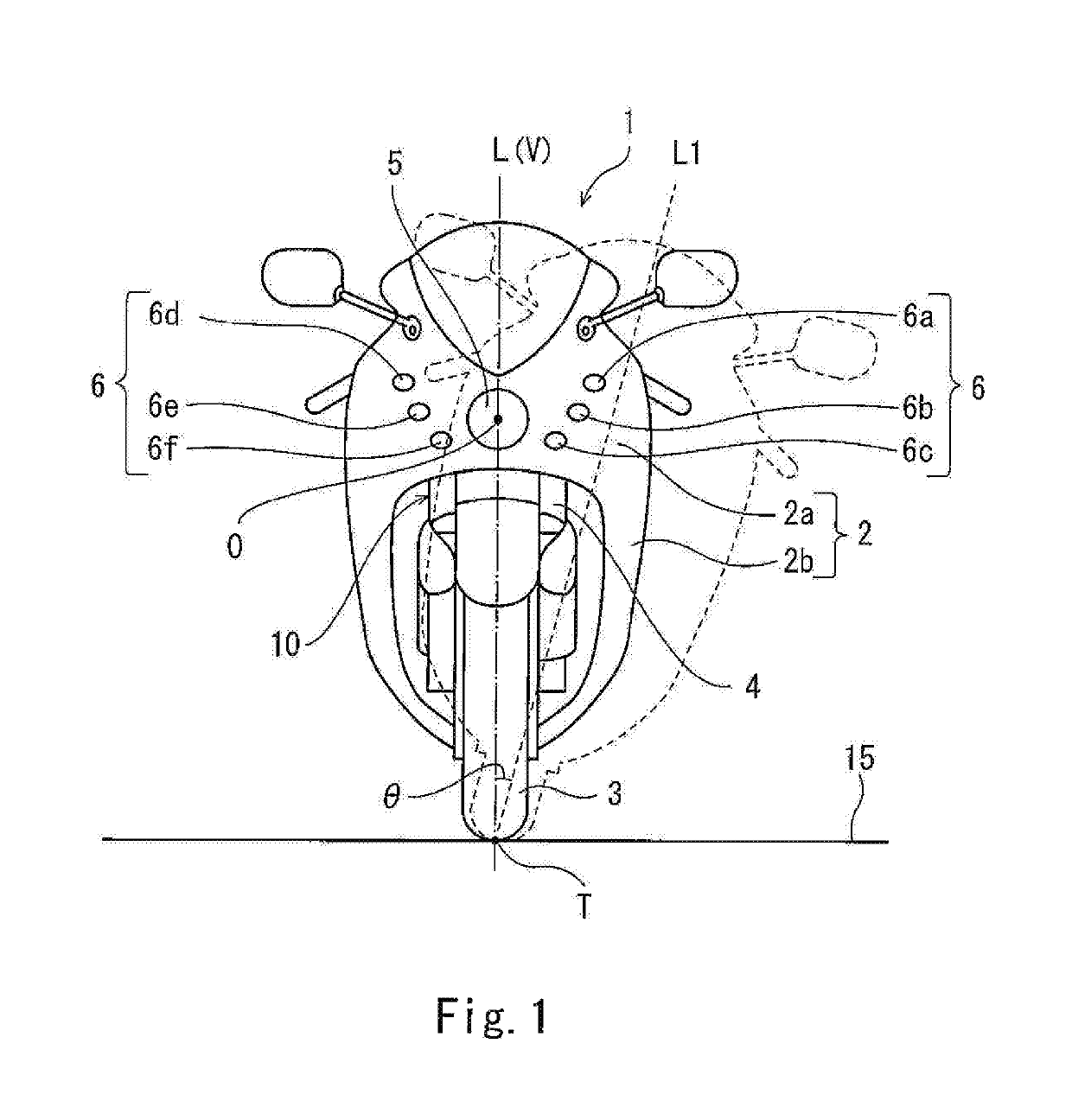
[0045]FIG. 1 is a front view of a motorcycle 1 according to Embodiment 1. As shown in FIG. 1, the motorcycle 1 includes a cowling 2 covering a vehicle body 10. The cowling 2 includes a front cowling 2a, and a side cowling 2b. A front fork 4 is rotatably coupled at a lower end portion thereof to a front wheel 3. The front cowling 2a covers the upper side of the front fork 4. The side cowling 2b is located rearward relative to the front cowling 2a and covers the vehicle body 10 from outer sides in the vehicle width direction. A head lamp 5 is attached to the front portion of the front cowling 2a. In the present embodiment, the head lamp 5 is a head lamp including a light emitting diode (LED) light source as a light source. The light source of the head lamp 5 is not limited to the LED light source, and may be a halogen lamp, a discharge lamp, etc. The head lamp 5 irradiates a head lamp irradiation region 50 set in a road surface 15 which is in front of the vehicle body 10 when the head...

embodiment 2

[0096]In the motorcycle according to Embodiment 2, the control for the lighting operations of the auxiliary lamps 6 according to Embodiment 1 is modified. Hereinafter, regarding the control for the lighting operations of the auxiliary lamps 6 according to Embodiment 2, differences from the control for the lighting operations of the auxiliary lamps 6 according to Embodiment 1 will be described.

[0097]FIG. 9 is a view showing the control performed for the lighting operations of the auxiliary lamps 6 according to Embodiment 2, corresponding to FIG. 3. As shown in FIG. 9, a preceding lighting state P202 of the second auxiliary lamp 6b includes an initial preceding lighting state P202a and a subsequent preceding lighting state P202b, while a preceding lighting state P203 of the third auxiliary lamp 6c includes an initial preceding lighting state P203a and a subsequent preceding lighting state P203b. In the lighting operation of the second auxiliary lamp 6b and the lighting operation of th...

embodiment 3

[0101]In the motorcycle according to Embodiment 3, the control for the lighting operations of the auxiliary lamps 6 according to Embodiment 2 is modified. Hereinafter, regarding the control for the lighting operations of the auxiliary lamps 6 according to Embodiment 3, differences from the control for the lighting operations of the auxiliary lamps 6 according to Embodiment 2 will be described.

[0102]FIG. 10 is a view showing the control performed for the lighting operations of the auxiliary lamps 6 according to Embodiment 3, corresponding to FIG. 3. As shown in FIG. 10, in a preceding lighting state P302 of the second auxiliary lamp 6b, an initial preceding lighting state P302a and a subsequent preceding lighting state P302b are discontinuous. More specifically, at a time point when the first auxiliary lamp 6a is lighted in the first set lighting state L1 at maximum luminosity, in a case where the second auxiliary lamp 6b is in the initial preceding lighting state P302a, the initial ...


PUM


Abstract

A vehicle comprises a head lamp which irradiates a head lamp irradiation region set in front of a vehicle body; an auxiliary lamp which irradiates an auxiliary lamp irradiation region set in front of the head lamp irradiation region; a bank state detecting section which detects a bank state of the vehicle body; and a lighting control section which lights the auxiliary lamp depending on the bank state, the lighting control section causes the auxiliary lamp to be lighted in a set lighting state when the bank state detecting section detects a predetermined set bank state, and the lighting control section causes the auxiliary lamp to be lighted in a preceding lighting state at luminosity lower than that of the set lighting state, when the bank state detecting section detects a preceding bank state which occurs before the vehicle body reaches the set bank state.

Description

CROSS-REFERENCE TO THE RELATED APPLICATION[0001]This application claims priority to and the benefit of Japanese Patent Application No. 2015-256647 filed on Dec. 28, 2015, the entire disclosure of which is incorporated herein by reference.BACKGROUND OF THE INVENTIONField of the Invention[0002]The present invention relates to a vehicle which turns in a state in which a vehicle body thereof is banked (tilted) from an upright state to one side in a vehicle width direction.Description of the Related Art[0003]In some cases, an exemplary vehicle such as a motorcycle turns in a state in which a vehicle body thereof is banked while the vehicle is traveling. For example, in a case where the vehicle turns in a state in which its vehicle body is banked from its upright state to the left, a region to be irradiated by a head lamp is lowered at the left from the perspective of a rider straddling the vehicle body. In other words, it becomes difficult for the head lamp to irradiate a region which is...

Claims


Application Information

Patent Timeline
Patent Type & Authority Patents(United States)
IPC IPC(8): B60R22/00B60Q1/10G06F17/00B60Q1/18B62J6/02B60Q1/04E05F15/00G05D1/00G05D3/00G06F7/00
CPCB60Q1/10B60Q1/0408B62J6/02B60Q1/18B62K2207/02B60Q2300/134B62J6/023B62J45/4151
Inventor SAKAMOTO, TAKUYAIWAMOTO, TAROTANI, OSAMU
Owner KAWASAKI MOTORS LTD
Why Eureka
Try Eureka