Supercharge Your Innovation With Domain-Expert AI Agents!

Transflective type liquid crystal display device

a liquid crystal display and reflector technology, applied in non-linear optics, instruments, optics, etc., can solve the problems of large battery, heavy weight, and increased power consumption of reflective type lcd devices, and achieve the effect of reducing the number of reflective devices

Active Publication Date: 2019-06-11
LG DISPLAY CO LTD
View PDF10 Cites 0 Cited by
  • Summary
  • Abstract
  • Description
  • Claims
  • Application Information

AI Technical Summary

Benefits of technology

The solution simplifies the fabrication process, enhances transmittance, improves contrast ratio, and reduces power consumption while maintaining high brightness and resolution, and offers improved viewing angles by aligning liquid crystal molecules uniformly across different areas.

Problems solved by technology

In the LCD device displaying an image of a high brightness, since a light of a high intensity of the backlight unit is required, a power consumption increases due to the backlight unit.
Further, for supplying a source power to the backlight unit of a high power consumption, a battery of a large amount and a heavy weight is required.
As a result, the reflective type LCD device may operate for a relatively long time to be used as a portable display device such as an electronic notebook and a personal digital assistant (PDA).
However, since it is impossible to use the reflective type LCD device under a situation of a weak ambient light or no ambient light, a transflective type LCD device having advantages of the reflective type LCD device and the transmissive type LCD device using the backlight has been suggested.
Since a step difference is formed between the transmissive area and the reflective area for the different cell gaps, a fabrication process becomes complicated and a yield is reduced.
Further, since the number of the gate lines and the number of the TFTs increase, deterioration of a fabrication process increases.

Method used


Image

  • Transflective type liquid crystal display device
  • Transflective type liquid crystal display device
  • Transflective type liquid crystal display device

Examples


first embodiment

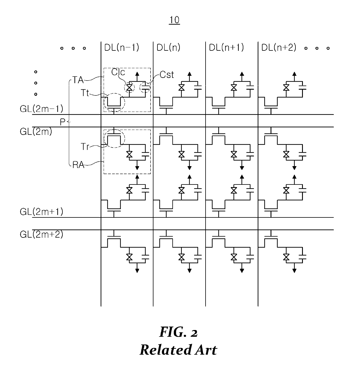
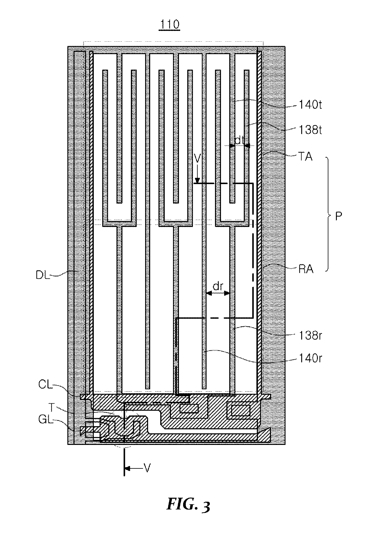
[0040]In FIGS. 3 and 4, a transflective type liquid crystal display (LCD) device 110 according to the present disclosure includes a plurality of gate lines GL(m−1), GL(m) and GL(m+1), a plurality of data lines DL(n−1), DL(n), DL(n+1) and DL(n+2) and a plurality of common lines CL. The plurality of gate lines GL(m−1), GL(m) and GL(m+1) and the plurality of data lines DL(n−1), DL(n), DL(n+1) and DL(n+2) cross each other to define a plurality of pixels P, and the plurality of common lines CL are spaced apart from and in parallel with the plurality of gate lines GL(m−1), GL(m) and GL(m+1). Each of the plurality of pixels P includes a transmissive area TA and a reflective area RA.

[0041]A gate electrode 122 (of FIG. 5A) of a thin film transistor (TFT) T is connected to the gate line GL(m−1), GL(m) and GL(m+1), and a source electrode 128 (of FIG. 5A) of the TFT T is connected to the data line c.

[0042]A plurality of reflective pixel electrodes 138r connected to a drain electrode 130 (of FIG...

second embodiment

[0089]In FIG. 6, a transflective type liquid crystal display (LCD) device 210 according to the present disclosure includes a plurality of gate lines GL, a plurality of data lines DL and a plurality of common lines CL. The plurality of gate lines GL and the plurality of data lines DL cross each other to define a plurality of pixels P, and the plurality of common lines CL are spaced apart from and in parallel with the plurality of gate lines GL. Each of the plurality of pixels P includes a transmissive area TA and a reflective area RA.

[0090]A gate electrode of a thin film transistor (TFT) T is connected to the gate line GL, and a source electrode of the TFT T is connected to the data line DL.

[0091]A plurality of reflective pixel electrodes 238r connected to a drain electrode of the TFT T and a plurality of reflective common electrodes 240r spaced apart from and in parallel with the plurality of reflective pixel electrodes 238r are formed in the reflective area RA.

[0092]A plurality of ...

third embodiment

[0108]In FIG. 7, a transflective type liquid crystal display (LCD) device 310 according to the present disclosure includes a plurality of gate lines GL, a plurality of data lines DL and a plurality of common lines CL. The plurality of gate lines GL and the plurality of data lines DL cross each other to define a plurality of pixels P, and the plurality of common lines CL are spaced apart from and in parallel with the plurality of gate lines GL. Each of the plurality of pixels P includes a transmissive area TA and a reflective area RA.

[0109]A gate electrode of a thin film transistor (TFT) T is connected to the gate line GL, and a source electrode of the TFT T is connected to the data line DL.

[0110]A plurality of reflective pixel electrodes 338r connected to a drain electrode of the TFT T and a plurality of reflective common electrodes 340r spaced apart from and in parallel with the plurality of reflective pixel electrodes 338r are formed in the reflective area RA.

[0111]A plurality of ...


PUM

PropertyMeasurementUnit
transmissive separation distance dtaaaaaaaaaa
diameteraaaaaaaaaa

Abstract

A liquid crystal display device includes: a substrate having a pixel including first and second areas; a thin film transistor on the substrate in the pixel; a first pixel electrode in the first area and connected to the thin film transistor; a first common electrode in the first area and spaced apart from the first pixel electrode by a first separation distance; a second pixel electrode in the second area and connected to the first pixel electrode; a second common electrode in the second area and spaced apart from the second pixel electrode by a second separation distance different from the first separation distance; and a liquid crystal layer on the first pixel electrode, the first common electrode, the second pixel electrode and the second common electrode.

Description

CROSS-REFERENCE TO RELATED APPLICATIONS[0001]The present application claims the benefit of priority of Korean Patent Application No. 10-2016-0162199 filed in the Republic of Korea on Nov. 30, 2016, which is hereby incorporated by reference in its entirety for all purposes as if fully set forth herein.BACKGROUNDTechnical Field[0002]The present disclosure relates to a liquid crystal display device, and more particularly to a transflective type liquid crystal display device displaying an image in a transmissive mode and a reflective mode.Discussion of the Related Art[0003]Recently, as the information age progresses, display devices processing and displaying a large amount of information have rapidly advanced. For example, various flat panel displays (FPDs) having a thin profile, a light weight and a low power consumption have been researched.[0004]As a result, a thin film transistor liquid crystal display (TFT-LCD) having an excellent color reproducibility and a thin profile has been d...

Claims


Application Information

Patent Timeline
Patent Type & Authority Patents(United States)
IPC IPC(8): G02F1/1343G02F1/1362G02F1/1335
CPCG02F1/1343G02F1/133555G02F1/134363G02F1/136286G02F1/133602G02F2001/134372G02F1/134309G02F1/134372G02F1/133528G02F1/13363G02F2201/121G02F2201/123
Inventor LEE, SANG-WOOKHWANG, JUNG-IMCHOI, MIN-GEUNJEON, JI-NA
Owner LG DISPLAY CO LTD
Features
  • R&D
  • Intellectual Property
  • Life Sciences
  • Materials
  • Tech Scout
  • Unparalleled Data Quality
  • Higher Quality Content
  • 60% Fewer Hallucinations
Learn More