Radio information terminal, radio communication system, and communicating method and program for use in the radio information terminal

a technology of radio information terminal and communication system, which is applied in the direction of diversity/multi-antenna system, electromagnetic wave modulation, modulation, etc., can solve the problems of reducing the transmission strength and reception sensitivity toward other mobile stations, and increasing the number of mobile stations that can be connected

Inactive Publication Date: 2002-04-04
HERA WIRELESS
View PDF7 Cites 17 Cited by
  • Summary
  • Abstract
  • Description
  • Claims
  • Application Information

AI Technical Summary

Benefits of technology

[0025] The object of the present invention is to provide a radio communication system and a mobile station for the system that increase the number of mobile stations that can be connected using fixed frequency resources, while maintaining communication quality.

Problems solved by technology

The adaptive array apparatus, in forming the directivity pattern, not only increases transmission strength and reception sensitivity towards a desired mobile station, but also reduces transmission strength and reception sensitivity toward other mobile stations.
However, a dramatic increase in the number of users of radio communication systems has put further pressure on frequency resources, even when the path division multiple access and wire less zone methods are used, leading to a demand to further increase the number of mobile stations that can be connected, while using fixed frequency resources.

Method used


Image

  • Radio information terminal, radio communication system, and communicating method and program for use in the radio information terminal
  • Radio information terminal, radio communication system, and communicating method and program for use in the radio information terminal
  • Radio information terminal, radio communication system, and communicating method and program for use in the radio information terminal

Examples


Embodiment Construction

[0084]

[0085] The radio base station in an embodiment of the present invention path division multiplexes a maximum of four signals on the same frequency according to path division multiple access, in addition to TDMA / TDD (Time Division Multiple Access / Time Division Duplex) determined by the PHS Standard, and connects wirelessly to mobile stations.

[0086]

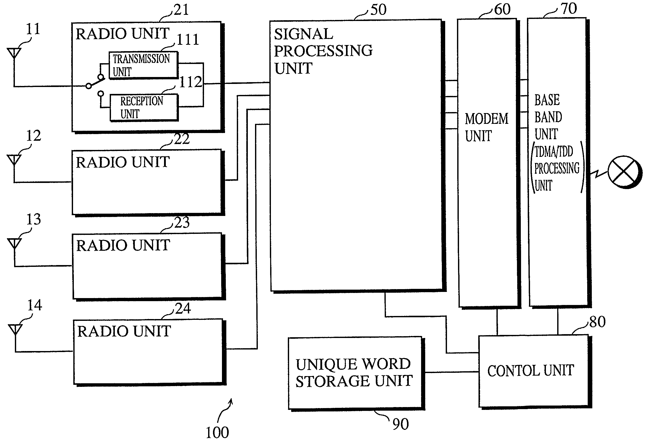
[0087] FIG. 1 is a block diagram of the structure of a radio base station 100 in an embodiment of the present invention.

[0088] The radio base station 100 is composed of antennas 11 to 14, radio units 21 to 24, a signal processing unit 50, a modem unit 60, a base band unit 70, a control unit 80, and a unique word storage unit 90.

[0089] The radio base station 100 multiplexes four channels in one TDMA / TDD frame and simultaneously processes a maximum of four telephone line signals to be path division multiplexed on one channel. One TDMA / TDD frame has a 5 ms time cycle, and is composed of four transmission time slots and four reception ti...


PUM


Abstract

The object of the present invention is to provide a radio communication system and a mobile station for the system that increase the number of mobile stations that can connect to the same frequency resource while maintaining communication quality. In order to achieve the stated object, the mobile station is notified of unique word information, which is different for each mobile station, from a radio base station through the control channel, stores the information in a UW information storage unit, modulates a synchronization code which includes the information into a reference signal through a re-modulation signal, and stores the result in a memory. When transmission and reception are performed on a link channel, a weight calculation unit forms directivity in the direction of the radio base station using the reference signal. By performing directivity control in the mobile station, interference signals radiated to other wireless zones are reduced while interference signals from other wireless zones are eliminated, therefore the space between re-use of frequencies can be shortened, and the number of mobile stations that can be accommodated in the same frequency resource can be increased.

Description

[0001] This application is based on application No. 2000-215098 filed in Japan, the content of which is hereby incorporated by reference.[0002] (1) Field of the Invention[0003] The present invention relates to a radio information terminal (hereinafter "mobile station") that connects to abase station, for example a telephone and a portable information communication device, and a radio communication system made up of the radio base station and the mobile station. In particular, the present invention relates to improved efficiency of frequency usage in the system.[0004] (2) Description of the Related Art[0005] Recently with the number of mobile stations, including portable telephones and portable communication devices, on the rise there is increasing demand in society for more effective use of frequency resources. Path division multiple access and the wireless zone system (the latter is also called the cellular system) are techniques which respond to this demand.[0006] Path division mu...

Claims


Application Information

Patent Timeline
Patent Type & Authority Applications(United States)
IPC IPC(8): H04B7/06H04B7/08
CPCH04B7/0617H04B7/086H04B7/0848
Inventor DOI, YOSHIHARU
Owner HERA WIRELESS
Why Eureka
Try Eureka