Automated disk-ejection apparatus and disk array having the same

a disk array and automatic technology, applied in the field of automatic disk arrays, can solve the problems of inability to meet the requirements of the company, the service of the company is stopped, and the design is almost inacceptable, and achieves the effect of convenient loading or unloading

Inactive Publication Date: 2002-07-11
ACARD TECH CORP
View PDF22 Cites 9 Cited by
  • Summary
  • Abstract
  • Description
  • Claims
  • Application Information

AI Technical Summary

Benefits of technology

0007] An object of the present invention is to provide an automated disk-ejection apparatus for use in a disk system. In accordance with an embodiment of the present invention, the disk system includes a disk box for housing a disk drive. The apparatus comprises: a handle for pulling out or pushing back the disk box; a pushing mechanism for pushing the handle; and a control circuit for

Problems solved by technology

However, as the number of disk units increases in a great scale, the above design using locks will encounter many problems.
The result of a host system crash could be so critic

Method used


Image

  • Automated disk-ejection apparatus and disk array having the same
  • Automated disk-ejection apparatus and disk array having the same
  • Automated disk-ejection apparatus and disk array having the same

Examples


first embodiment

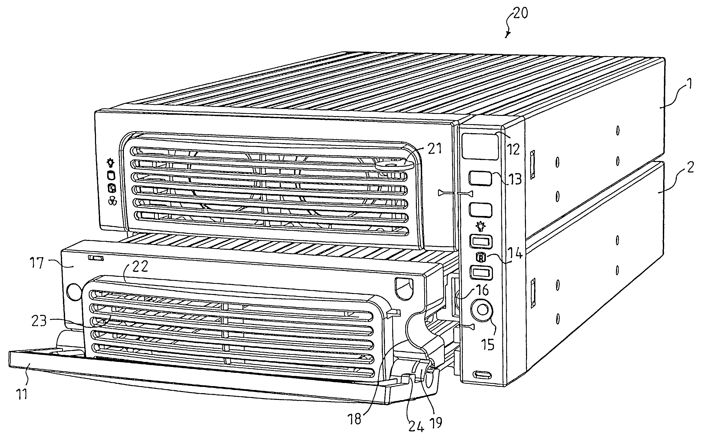
[0020] FIG. 4 shows the system according to the present invention. The disk box 2 comprises a panel 17. The handle 11 for pulling out the disk box 2 is connected to the disk box panel via a pivot 19. At one vertical side edge (right side in FIG. 4) of the panel 17, there is a groove 18 for accommodating a protrusion 24 of the handle 11, as well as for being the passage of the pushing mechanism (described later). The pushing mechanism 16 is controlled by a control circuit. The control circuit can be designed such that while a failure of a disk drive in the disk box 2 is detected, or the disk drive needs to be replaced, the control circuit controls and drives the pushing mechanism 16 by using a solenoid valve or an electric motor. The pushing mechanism 16 thus passes through the side groove 18 of the panel 17 to push the handle 11. The handle 11 can rotate to an eject state for a user to pull out the disk box 2.

[0021] In the system shown in FIG. 4, the handle 11 is connected to the di...

second embodiment

[0024] FIG. 5 illustrates a disk array system in accordance with the present invention. The disk array system 30 comprises disk boxes 31 and 32. Each of the disk boxes 31 and 32 comprises a rotatable panel 34. The panel 34 is connected to the disk box via a side pivot 35. It is clearly shown in FIG. 5 that the pushing mechanism 33 is used to push the rotatable panel 34 of the disk box. In a preferred embodiment, a solenoid valve or an electric motor can be used to release a latch of the panel 34 and push the panel 34 to rotate along the pivot 35, for a user to pull (or push) the panel 34 to withdraw (or restore) the disk box 31.

third embodiment

[0025] FIG. 6 illustrates a disk array system in accordance with the present invention, in which the disk array system 40 includes disk boxes 41 and 42. Each disk box 41 or 42 has a rotatable panel 44, and the panel 44 is connected to the disk box via a pivot 45 located at the lower part of the front surface of the disk box. In the embodiment disclosed in FIG. 6, a pushing mechanism is used to push the rotatable panel 44. After the panel 44 rotates along the pivot 45 to an inoperative state, a user can pull (or push) a handle 46 on the disk box 42 to withdraw (or inserst) the disk box 41.

[0026] Furthermore, because the pushing mechanisms 33 and 43 shown in FIGS. 5 and 6 are located at the front surfaces of housings of the disk array systems 30 and 40, the pushing mechanisms will not move along with the movement of each disk box 31, 32, 41 or 42. However, it should be noted that pushing mechanisms 33 or 43 can be located at the front surfaces of the disk boxes 31, 32, 41 and 42. Unde...


PUM


Abstract

Disclosed is an automated disk-ejection apparatus for use in a disk system. The disk system includes a disk box for housing a disk drive, and the auto-ejection apparatus comprises: a handle for pulling out or pushing back the disk box; a pushing mechanism for pushing the handle; and a control circuit for controlling the pushing mechanism. The featured disk apparatus is designed such that while the disk box needs to be pulled out in order for loading or replacing the disk drive, the pushing mechanism is activated to push the handle. The handle can thus be rotated along the pivot into an inoperative state, for subsequently to be pulled for withdrawing the disk box. Moreover, another embodiment of the present invention relates to using a pushing mechanism to push a rotatable panel of a disk box.

Description

BACKGROUND OF THE PRESENT INVENTION[0001] The present invention relates to an automated disk-ejection apparatus, for use in an information storage device such as a disk drive, and particularly, to a hard disk box. The automated disk-ejection apparatus provides a handle or panel, which can be auto-ejected such that a user can easily withdraw the disk box for loading or replacing the disk drive. Moreover, the automated disk-ejection may also comprise a status indicator to clearly indicate the operation status, in accordance with auto-ejection of the handle. The status indicator can remind the user to plug or unplug the disk box correctly, so as to avoid that the host computer coupled to the disk box becomes down due to fault actions. The functions of auto-ejection and auto-indication are particularly important in the applications of disk arrays. As a result, the present invention provides a quite useful and intelligent automated disk-ejection apparatus.[0002] In this information era, ...

Claims


Application Information

Patent Timeline
IPC IPC(8): G11B17/038G11B17/22G11B33/12
CPCG11B17/038G11B17/221G11B33/125
Inventor WENG, MAO-HUAIWU, CHIA-CHANGCHEN, PO-YAOWU, DERYILIEN, PING-HUA
Owner ACARD TECH CORP
Why Eureka
Try Eureka