Controllable sealed chamber for surveillance camera

a sealed chamber and surveillance camera technology, applied in the field of surveillance camera systems, can solve the problems of inability to compensate, damage, shorten the life of the enclosure, and limited adaptability of the enclosure,

Inactive Publication Date: 2002-10-03
PELCO INC
View PDF29 Cites 71 Cited by
  • Summary
  • Abstract
  • Description
  • Claims
  • Application Information

AI Technical Summary

Problems solved by technology

Many existing outdoor camera housing enclosures include fans and/or heaters to help control the interior environment, but they are not sealed.
As a result, such enclosures have limited ability to adapt to changing climactic conditions.
More importantly, they are unable to compensate for changes in pressure and humidity that can be particularly harmful to the delicate internal electronics and camera optics of surveillance camera systems, and that may impair, damage or shorten the life of these components.
However, these simple sealed enclosures do not compensate for changes in pressure so that, over time, changes in air pressure may result in the rupture of the housing seal(s) exposing the internal electronics and camera to the damaging effects of the external environment.
However, this device only solves part of the problem since it does not mai...

Method used


Image

  • Controllable sealed chamber for surveillance camera
  • Controllable sealed chamber for surveillance camera
  • Controllable sealed chamber for surveillance camera

Examples


Embodiment Construction

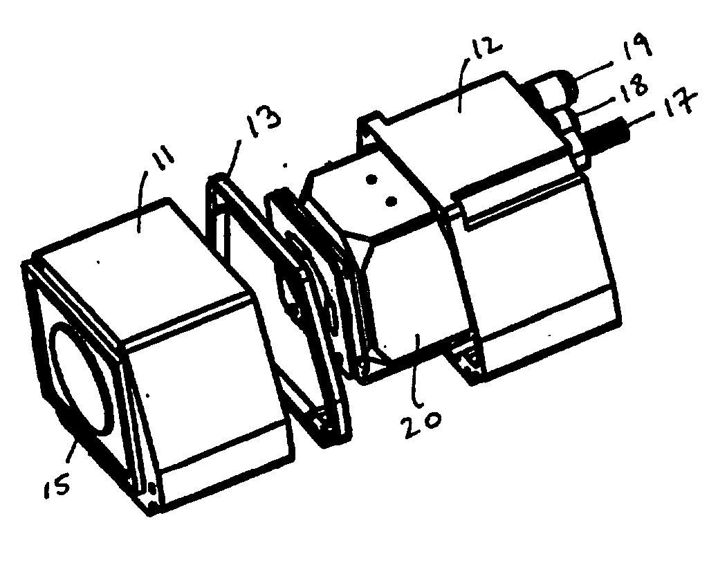
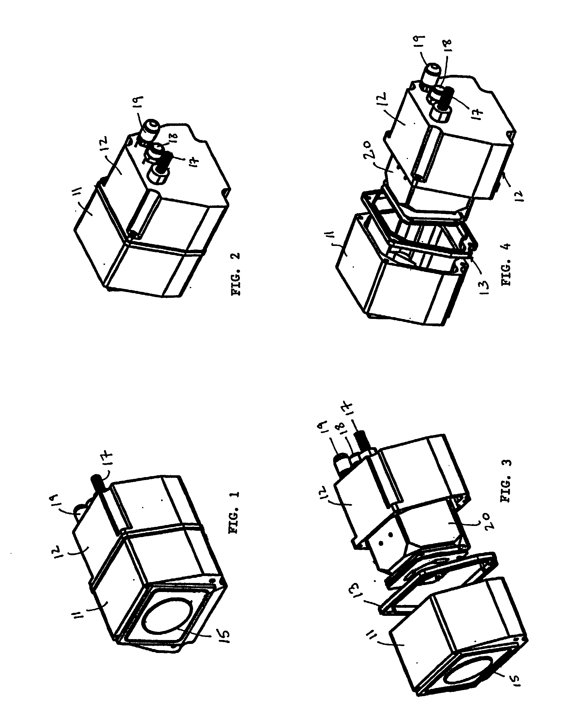
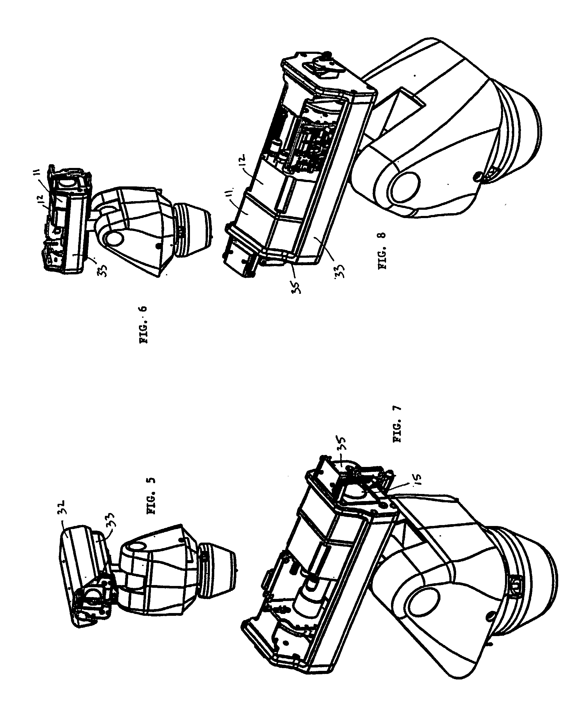
[0030] Referring to the drawings wherein like reference characters designate like or corresponding parts throughout the several views, and referring particularly to FIGS. 1-4, it is seen that the chamber of the present invention includes a front housing or outer shell 11, a rear housing or outer shell 12, and a gasket 13 for sealingly connecting shell 11 to shell 12 to form a sealed chamber 11-12. Front shell 11 is provided with a transparent window 15 for flush mounting with the front 35 of external housing 33 (see FIG. 7). Rear shell 12 is provided with a sealed feed through connector 17 so that pressure may be maintained inside chamber 11-12 while electronic signals may be sent to and from camera 20 inside. Rear shell 12 is also provided with an input valve 19 and an output valve 18. Input valve 19 is provided to allow chamber 11-12 to be filled with an appropriate gas, preferably inert, and preferably moisture-free. Purge valve 18 is provided to allow gas, dust and moisture to b...


PUM


Abstract

A chamber for a surveillance camera that is designed to be mounted inside a larger camera housing. The chamber is sealed and provides a controlled internal environment for sensitive camera optics and internal electronics. A flush mount window is provided for the front lens of the camera, and a sealed feed-through electronic connector is provided for attachment to external controls. Valves for both adding and removing gasses to/from the chamber are provided. In one embodiment, temperature, pressure and/or humidity sensors may be deployed inside the chamber and connected electronically to a display or computer for monitoring and adjustment. In another embodiment of, a heating element is provided to evaporate moisture from the camera lens and/or from the window, and to help control the temperature inside the chamber.

Description

[0001] This application claims the benefit of U.S. provisional application No. 60 / 280,715 filed on Mar. 30, 2001, and of U.S. design patent application No. 29 / 139,520 filed on Mar. 30, 2001.[0002] 1. Field of the Invention.[0003] The present invention relates to surveillance camera systems, and more particularly to a mounting apparatus including a controllable sealed chamber or enclosure for a surveillance camera (pressurized ESPRIT) designed to be mounted inside a larger camera housing in order to provide the camera and its associated electronics with a controlled and monitored atmosphere.[0004] 2. Description of the Prior Art[0005] The use of surveillance cameras and related systems is becoming increasingly more prevalent. Not only are surveillance cameras used in such traditional institutions as banks and casinos, but their use has spread to retail and business establishments, indoor and outdoor entry points, airport security checkpoints, government buildings, and the like.[0006]...

Claims


Application Information

Patent Timeline
IPC IPC(8): H04N5/225
CPCH04N5/2252G08B13/19619H04N23/51
Inventor COOPER, CLIFF LAWRENCECOCKRUM, JOSHUA RYANHIGGINS, MICHAEL TIMOTHYCOMPTON, SHANE E.
Owner PELCO INC
Why Eureka
Try Eureka