

Enhanced wireless communication system and method thereof
- Summary
- Abstract
- Description
- Claims
- Application Information
AI Technical Summary
Benefits of technology
Problems solved by technology
Method used
Image

Examples
Embodiment Construction
[0002] 1. Field of the Invention
[0003] This invention pertains in general to a communication system and, more particularly, to a third generation wireless communication system.
[0004] 2. Background of the Invention
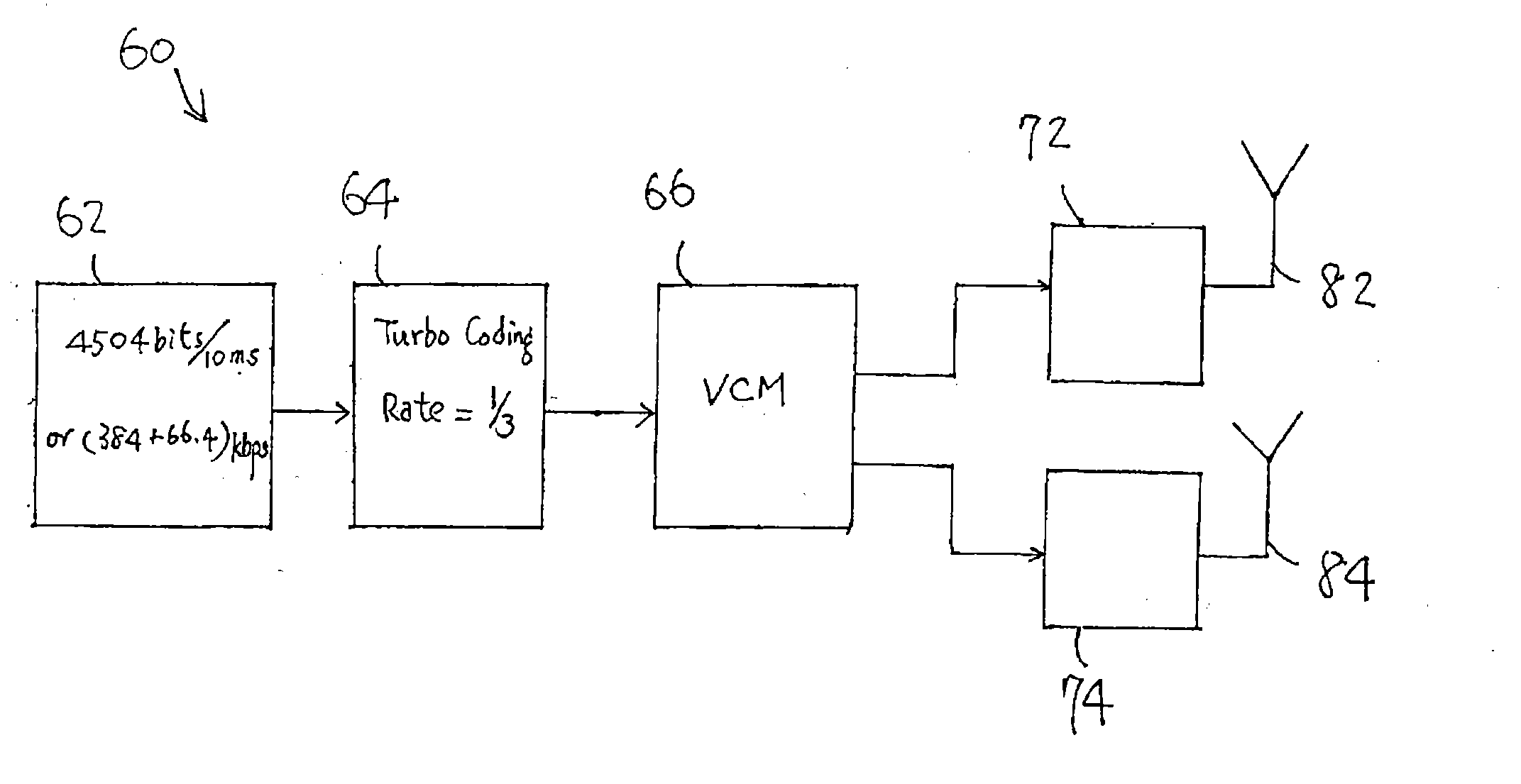
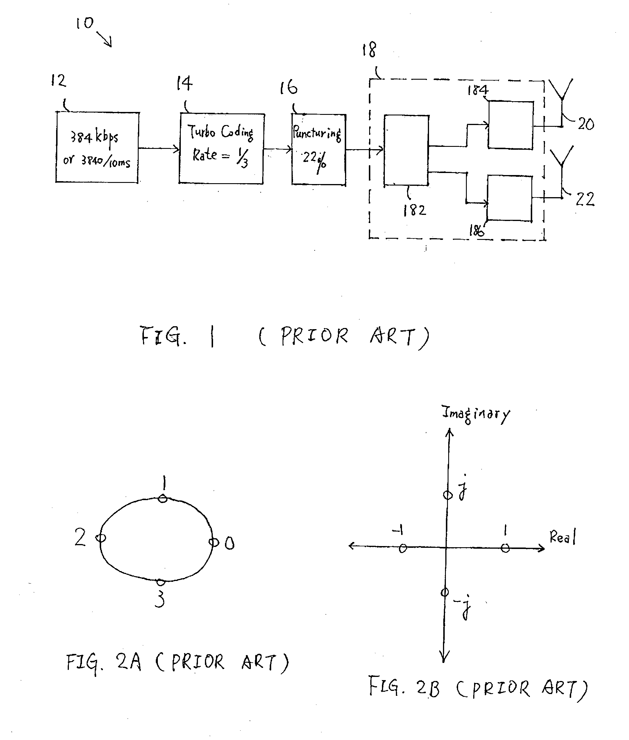
[0005] Modern wireless communication services should be able to provide high-speed data transmission for multimedia applications. For "third-generation" telecommunication systems, the ability to provide increased system capacity and data rate for individual users are some of the objectives. Generally in such systems, downlink transmission from a base station to a mobile station is more significant than uplink transmission because the asymmetric nature of Internet traffic such as web browsing and file transfer protocol ("FTP") downloads. An approach to enhance data transmission rate and efficiency over wireless channels employs coding techniques and multiple transmitter antennas. Such an approach has been discussed, for example, in "Simplified Processing for High Spectral Ef...
PUM
 Abstract
Description
Claims
Application Information