Regfrigerating device

a refrigeration device and refrigerating technology, applied in refrigeration safety arrangements, refrigeration components, light and heating apparatuses, etc., can solve the problems of complicated control performed in accordance with operating status, and achieve the effect of easy switching control, increased cop, and increased cop

Inactive Publication Date: 2004-06-17
DAIKIN IND LTD
View PDF6 Cites 28 Cited by
  • Summary
  • Abstract
  • Description
  • Claims
  • Application Information

AI Technical Summary

Benefits of technology

0023] Besides, according to the second solution, only by switching the four-way selector valve (3C) between the first state and the second state, the second compressor means (2B) can be switched between the first channel and the second channel, thus making it possible to carry out the switching control with ease.
0024] Moreover, according to the third solution, the gas refrigerant evaporated in the cooling heat exchangers (45, 51), and the gas refrigerant evaporated in the air conditioning heat exchanger (41) are sucked into the compressor means (2D) in the first channel and the compressor means (2E) in the second channel, respectively; therefore, the pressure of a low-pressure refrigerant in the air conditioning heat exchanger (41) and that of a low-pressure refrigerant in the cooling heat exchangers (45, 51) can be made different from each other. That is, by making the refrigerant evaporation temperature in the air conditioning heat exchanger (41) different from that in the cooling heat exchangers (45, 51), it becomes possible to carry out a so-called "dual evaporation temperature operation" in which the refrigerant evaporation temperature in the air conditioning heat exchanger (41) is high and that in the cooing heat exchangers (45, 51) is low.
0025] Further, by evaporating the refrigerant in the air conditioning heat exchanger (41) and that in the cooling heat exchangers (45, 51) at different temperatures, an increase in COP (coefficient of performance) can be achieved. In other words, the evaporation temperature in the air conditioning heat exchanger (41) which is required in an air conditioning (air-cooling) operation, and the evaporation temperature in the cooling heat exchangers (45, 51) which is required in a cooling operation can each be optimized, thus achieving an increase in the COP.
0026] Furthermore, according to the fourth solution, by switching, for example, the four-way selector valve (3C) between the first state and the second state, switching among air conditioning operation, cooling (cold storage / freezing) operation, and air conditioning and cooling operation is allowed with ease.
0027] In addition, according to the sixth solution, the second compressor means (2B) can be easily switched to the first channel for a cold storage / freezing operation, for example, or to the second channel for an air conditioning operation, for example, like the above-described solutions, and even if a capacity deficiency occurs in either of the channels, the capacity deficiency can be redressed.
0028] Moreover, according to the seventh solution, since the capacity of the first channel and that of the second channel are assigned priorities, an operation in which a higher priority is given to the cold storage / freezing capacity is enabled in a system including a cold storage / freezing channel and an air conditioning channel. As a result, the quality of refrigerated foods or frozen foods, for example, can be maintained with certainty.

Problems solved by technology

Furthermore, in the refrigerating apparatus, in order to realize various operating patterns of the compressor means, complicated control performed in accordance with operating status is also needed.

Method used


Image

  • Regfrigerating device
  • Regfrigerating device
  • Regfrigerating device

Examples


Embodiment Construction

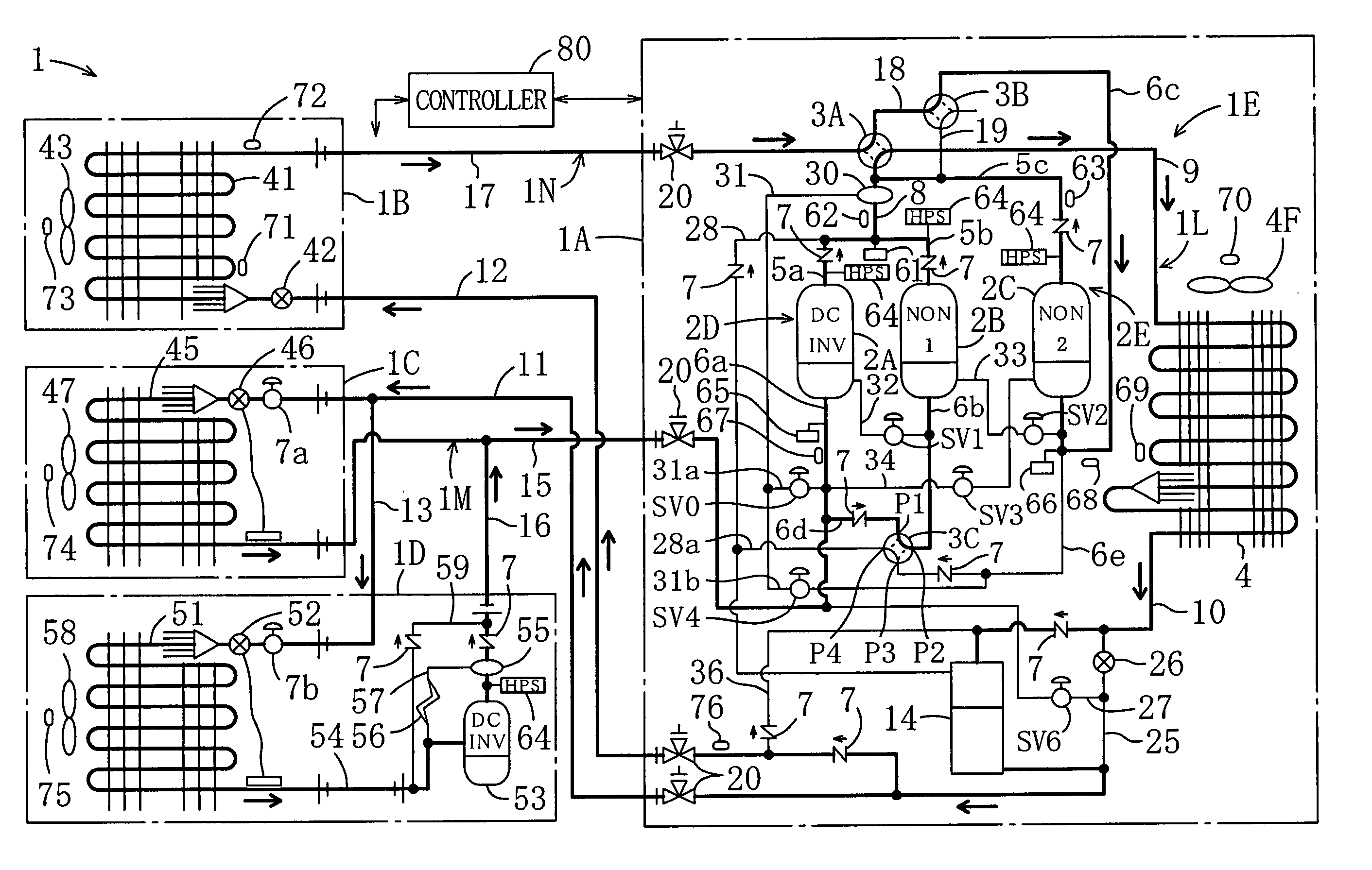
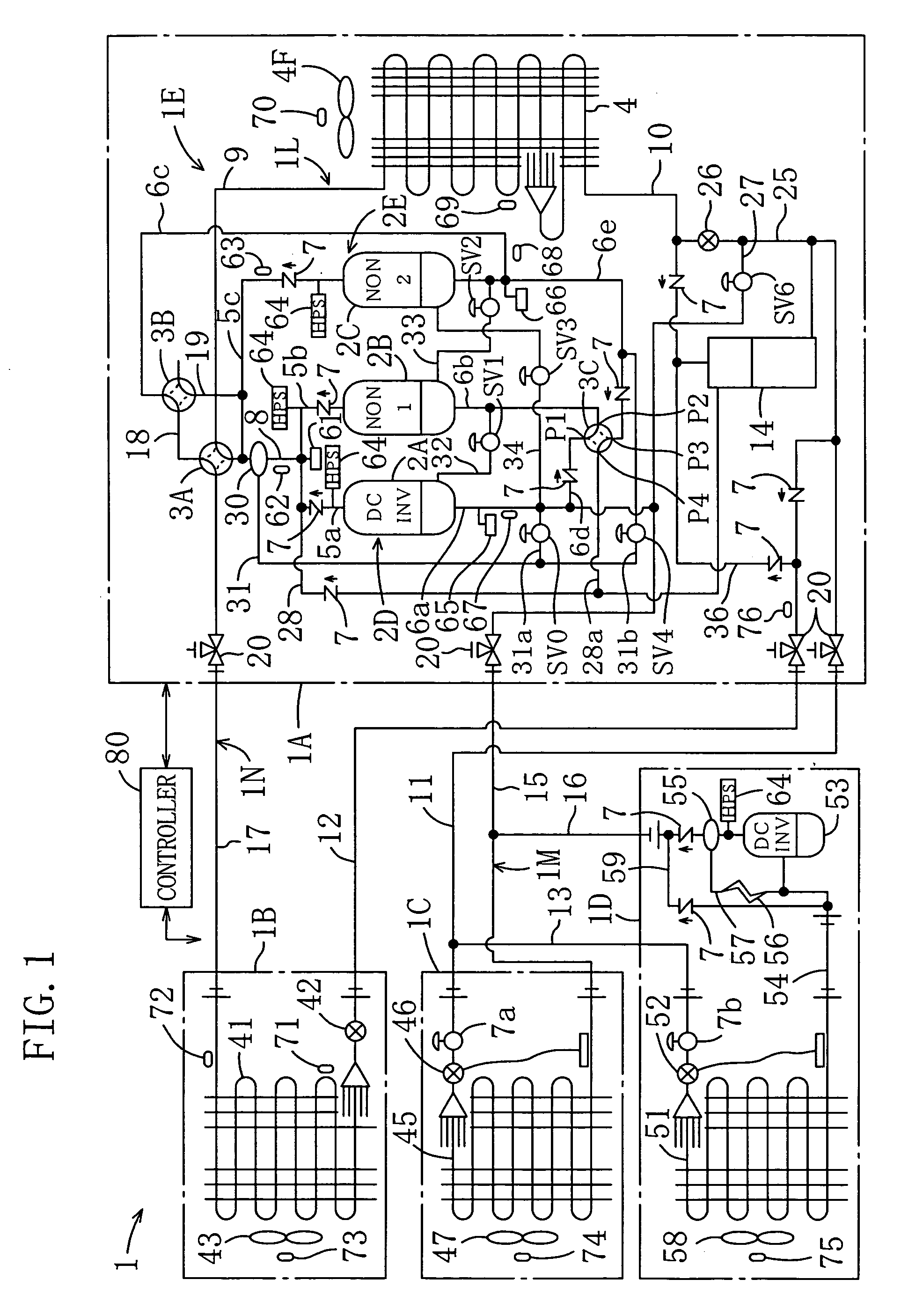
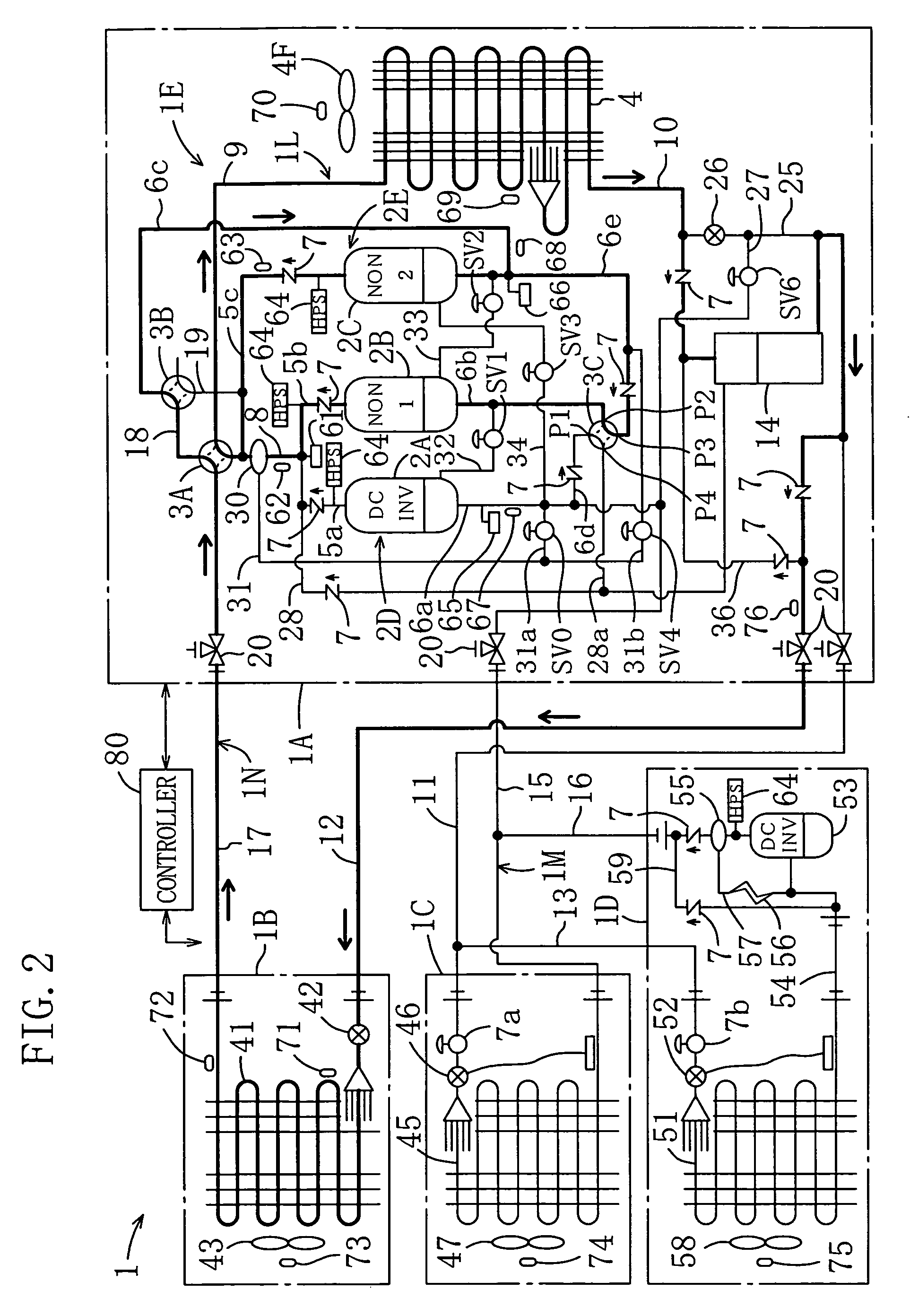
[0040] Hereinafter, an embodiment of the present invention will be described in detail with reference to the drawings.

[0041] As shown in FIG. 1, a refrigerating apparatus (1) according to the present embodiment is installed in a convenience store, and is allowed to cool showcases and air-cool and air-heat the inside of the store.

[0042] The refrigerating apparatus (1) includes: an outdoor unit (1A); an indoor unit (1B); a cold storage unit (1C); a freezing unit (1D); and a refrigerant circuit (1E) for carrying out a vapor compression refrigeration cycle. The refrigerant circuit (1E) includes: a first channel side circuit for a cold storage / freezing operation; and a second channel side circuit for an air conditioning operation. The refrigerant circuit (1E) is formed to allow switching between an air-cooling cycle and an air-heating cycle.

[0043] The indoor unit (1B) is formed to carry out an air-cooling operation and an air-heating operation in a switchable manner, and is installed at ...


PUM


Abstract

A refrigerating apparatus including three compressors (2A, 2B, 2C) and application side heat exchangers (41) (45, 51) for two channels is formed so that a first compressor (2A) is used only for the application side heat exchangers (45, 51) in a first channel of a circuit, a third compressor (2C) is used only for the application side heat exchanger (41) in a second channel of the circuit, and a second compressor (2B) is used in a switchable manner between the application side heat exchangers (45, 51) in the first channel of the circuit and the application side heat exchanger (41) in the second channel of the circuit. Thus, not only the pipe arrangement at suction side is simplified, but also operation control is streamlined.

Description

[0001] The present invention relates to a refrigerating apparatus, and more particularly relates to a refrigerating apparatus in which compressor mechanisms are formed by combining three compressor means.[0002] A refrigerating apparatus for carrying out a refrigeration cycle has conventionally been known, and has widely been used as an air conditioner for cooling and heating the air in a room, and a cooler such as a refrigerator, a freezer or a showcase for storing foods. As disclosed in WO98 / 45651, some refrigerating apparatuses of this type carry out both of an air conditioning operation and a cold storage / freezing operation. For example, a refrigerating apparatus of this type includes application side heat exchangers for two channels such as an air conditioning heat exchanger and a cooling heat exchanger for a cold storage / freezing operation, and is installed in a convenience store and the like.[0003] Actually, in order to widely change compressor displacement in accordance with ...

Claims


Application Information

Patent Timeline
Patent Type & Authority Applications(United States)
IPC IPC(8): F25B1/10F25B13/00
CPCF25B1/10Y02B30/741F25B2313/005F25B2313/0231F25B2313/02331F25B2313/02344F25B2313/02743F25B2313/0292F25B2313/0314F25B2313/0315F25B2400/061F25B2400/075F25B2400/0751F25B2400/19F25B2400/22F25B2600/021F25B2600/0251F25B2700/1931F25B2700/21152F25B13/00Y02B30/70F25B5/02
Inventor TANIMOTO, KENJITAKEGAMI, MASAAKISAKAE, SATORU
Owner DAIKIN IND LTD
Why Eureka
Try Eureka