

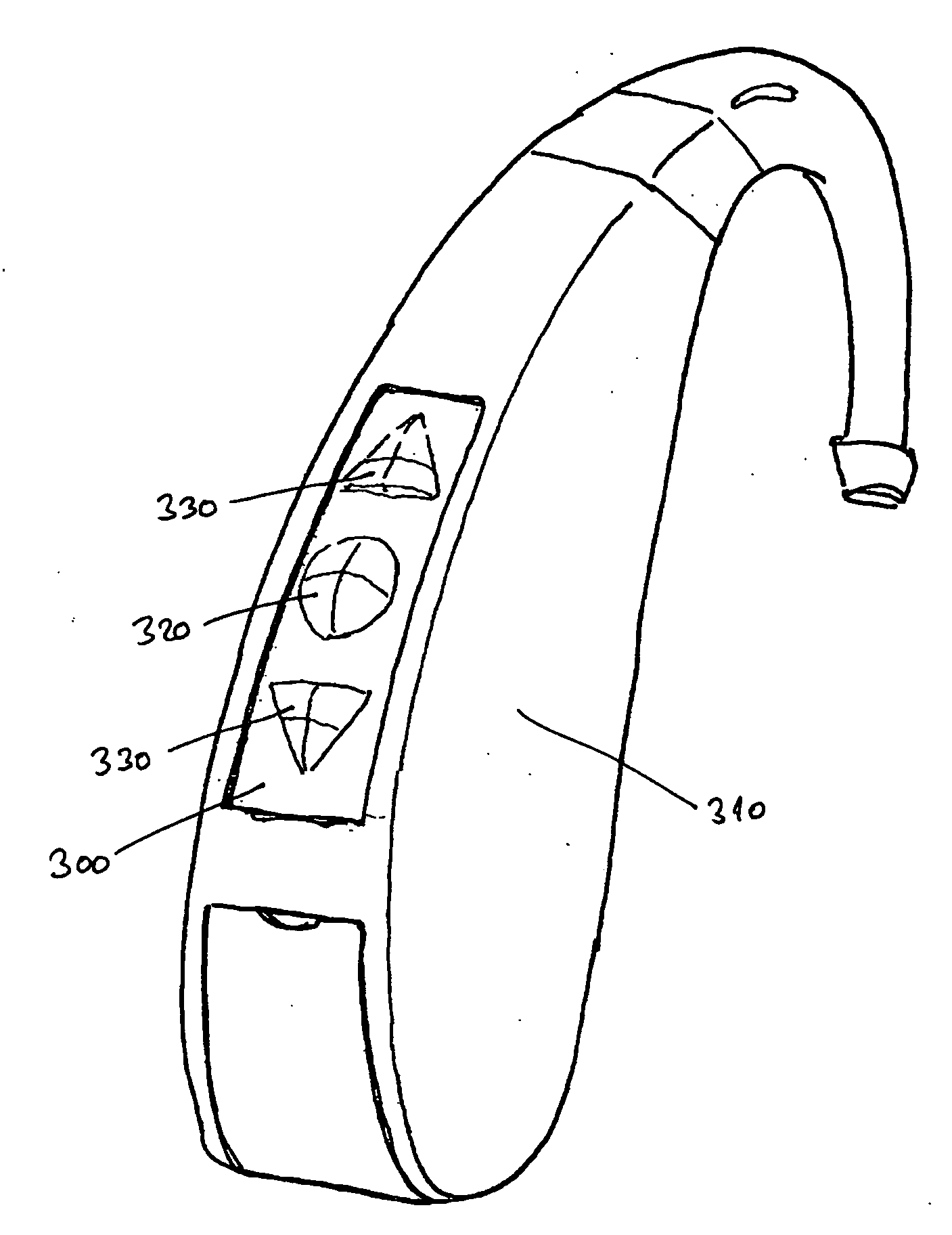
Control panel with activation zone
a control panel and activation zone technology, applied in the direction of emergency contacts, electrical appliances, basic electric elements, etc., can solve the problems of permanent damage to the hearing aid, difficult cleaning, and disturbance of the function of the hearing aid, and achieve the effects of convenient cleaning, low cost, and easy changeability
- Summary
- Abstract
- Description
- Claims
- Application Information
AI Technical Summary
Benefits of technology
Problems solved by technology
Method used
Image

Examples
Embodiment Construction
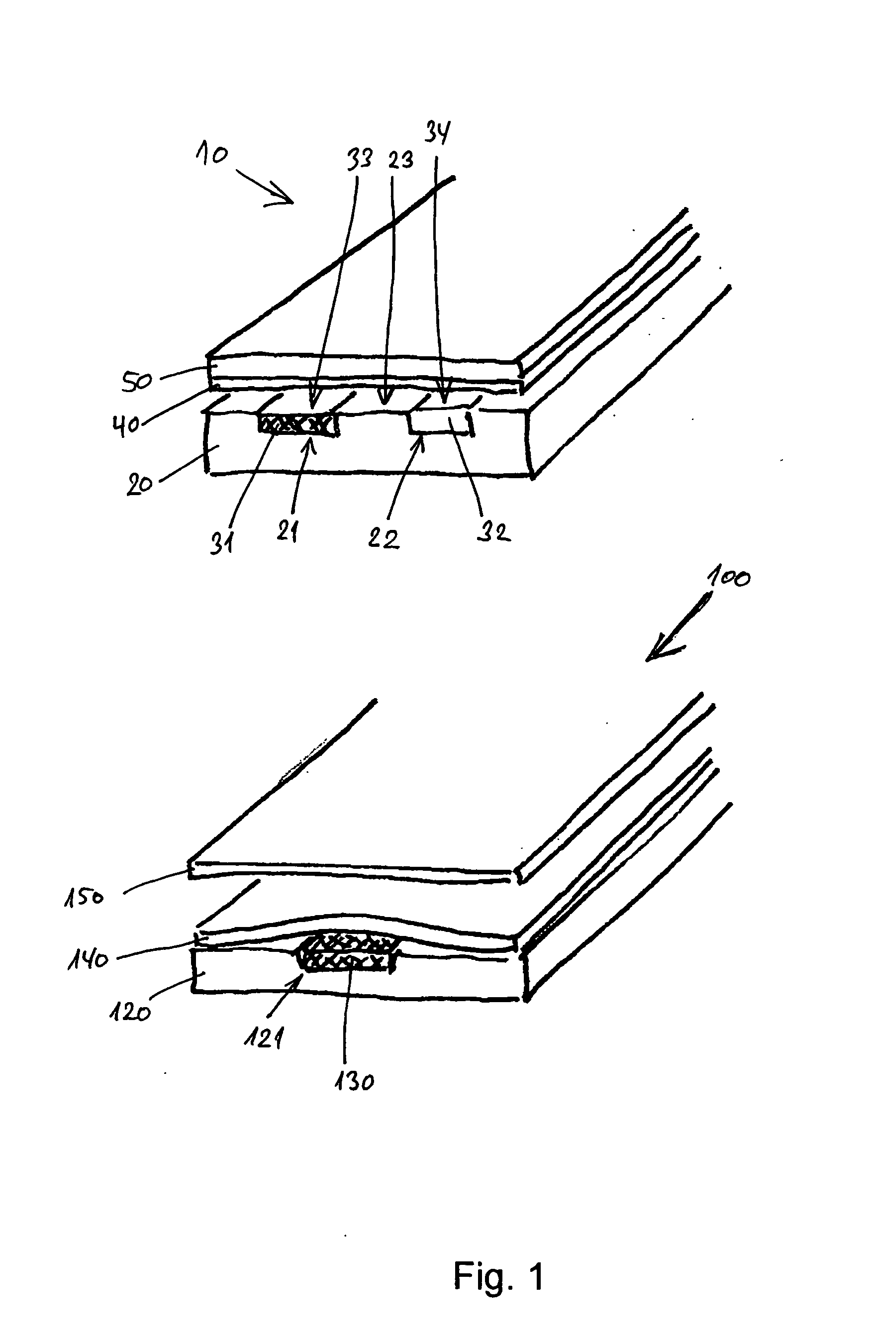
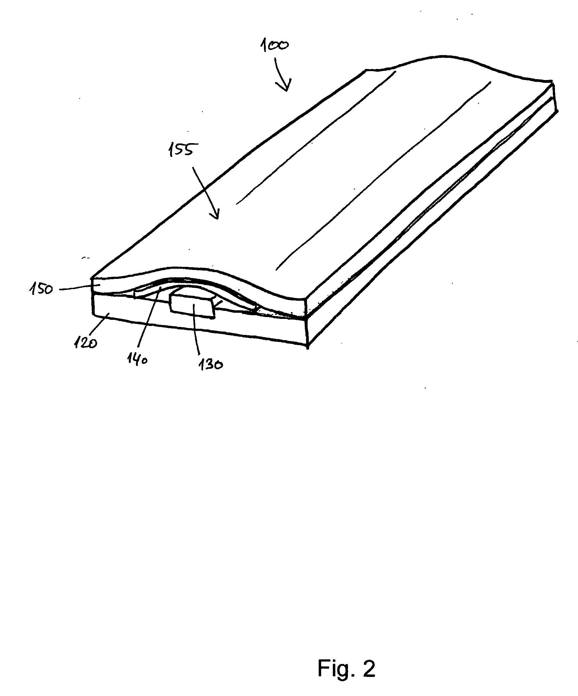
[0051]FIG. 1 shows cross sections of two ways of providing an activation zone of a control panel according to the present invention.
[0052] Upper part of FIG. 1 shows a first control panel 10 comprising an electrically non-conducting substrate 20 with a first recess 21 and a second recess 22. The substrate 20 is substantially flat. A first electrical conducting path 31 is positioned in the first recess 21 and a second electrical conducting path 32 is positioned in the second recess 22. The conducting paths 31,32 are positioned so that they are not in electrical connection. An upper surface 33 of the first conducting path 31 is substantially in plane with an upper surface 23 of the substrate 20. It may be preferred that the upper surfaces 33,34 of the two conducting paths 31,32 are positioned slightly above the surface 23 of the substrate 20. An electrically conducting member 40 formed as a foil of an electrically conducting material is positioned a certain distance above the upper s...
PUM
 Abstract
Description
Claims
Application Information