Projector

a projector and heat dissipation plate technology, applied in the field of projectors, can solve the problems of difficult to obtain a sufficient heat dissipation effect, and after, and achieve the effect of effectively controlling the rise in the temperature of the dmd device, improving the heat dissipation effect of the heat radiating plate, and increasing the surface area

Inactive Publication Date: 2005-01-20
FUNAI ELECTRIC CO LTD
View PDF7 Cites 91 Cited by
  • Summary
  • Abstract
  • Description
  • Claims
  • Application Information

AI Technical Summary

Benefits of technology

[0023] In the projector according to this second aspect, as described above, the heat radiating fin portion is provided on the heat radiating plate for radiating the heat of the DMD device, and the through hole is provided in the heat radiating fin portion. Therefore, it is possible to increase the surface area of the heat radiating fin portion by the portion of the surface area of the through hole. Consequently, it is possible to improve the heat dissipation effect of the heat radiating plate. For this reason, it is possible to effectively control the rise in the temper...

Problems solved by technology

For this reason, there has been a drawback in that it is difficult to obtain a sufficient heat dissipation effect.
For this reason, even if the number or sizes of the heat radiating fin portions 120c are increased to some extent, it is, after all, difficult to obtain a sufficient heat dissipation effect.
As a result, there has been a problem in that it is difficult to effectively control the rise in the temperature of the DMD device 115.
In addition, also in the projectors disclosed in JP-A-2002-90886 and JP-A-2002-174795 ment...

Method used


Image

  • Projector
  • Projector
  • Projector

Examples


Embodiment Construction

[0032] Hereafter, a description will be given of an embodiment of the invention with reference to the drawings.

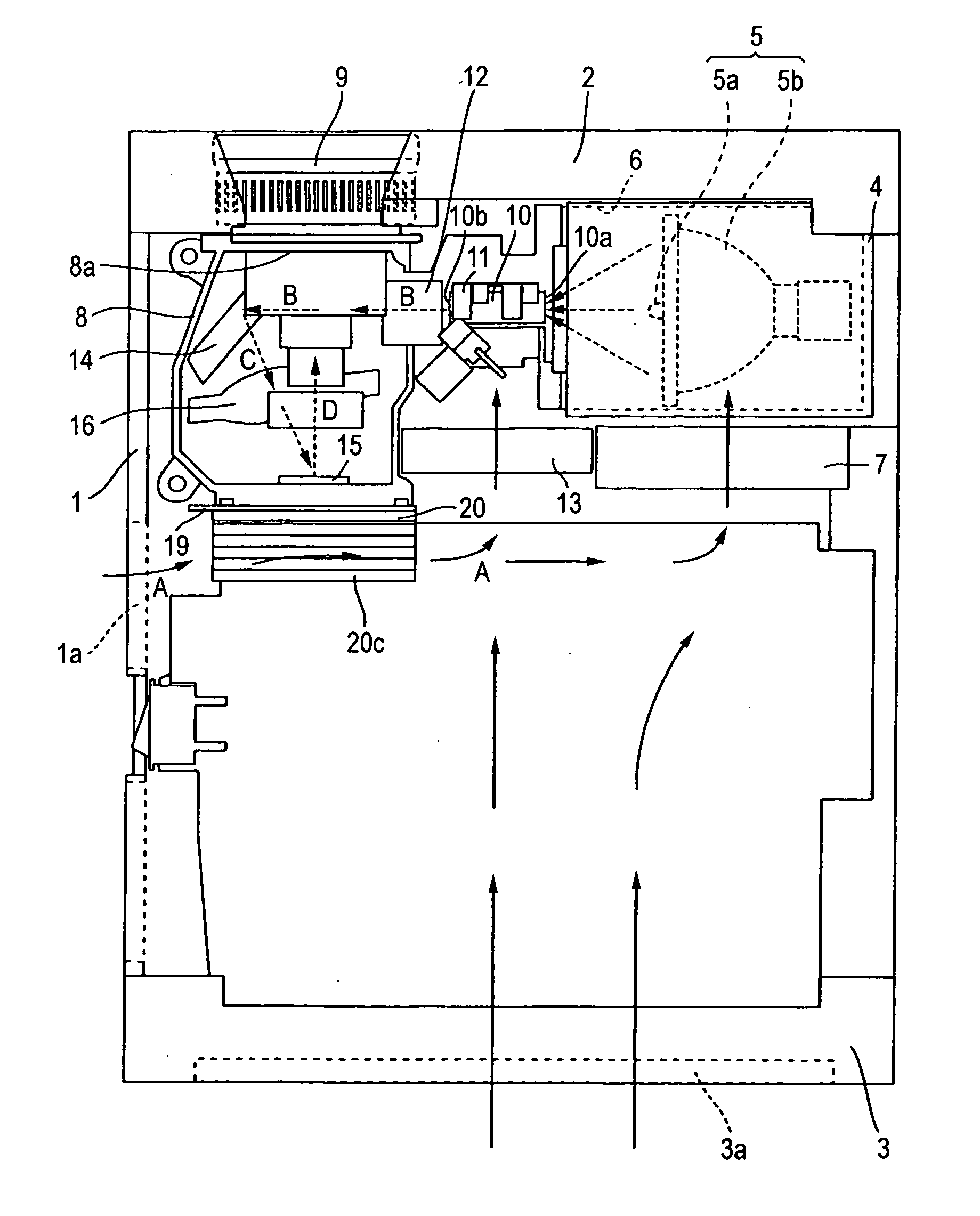
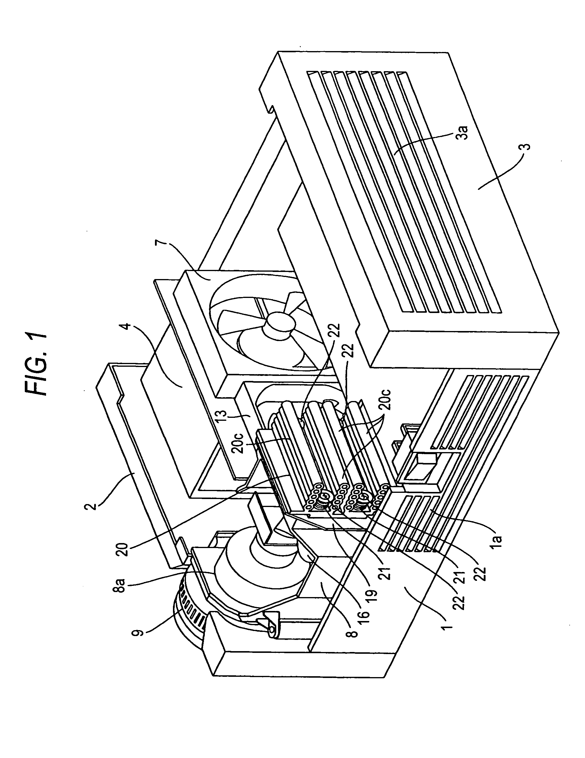
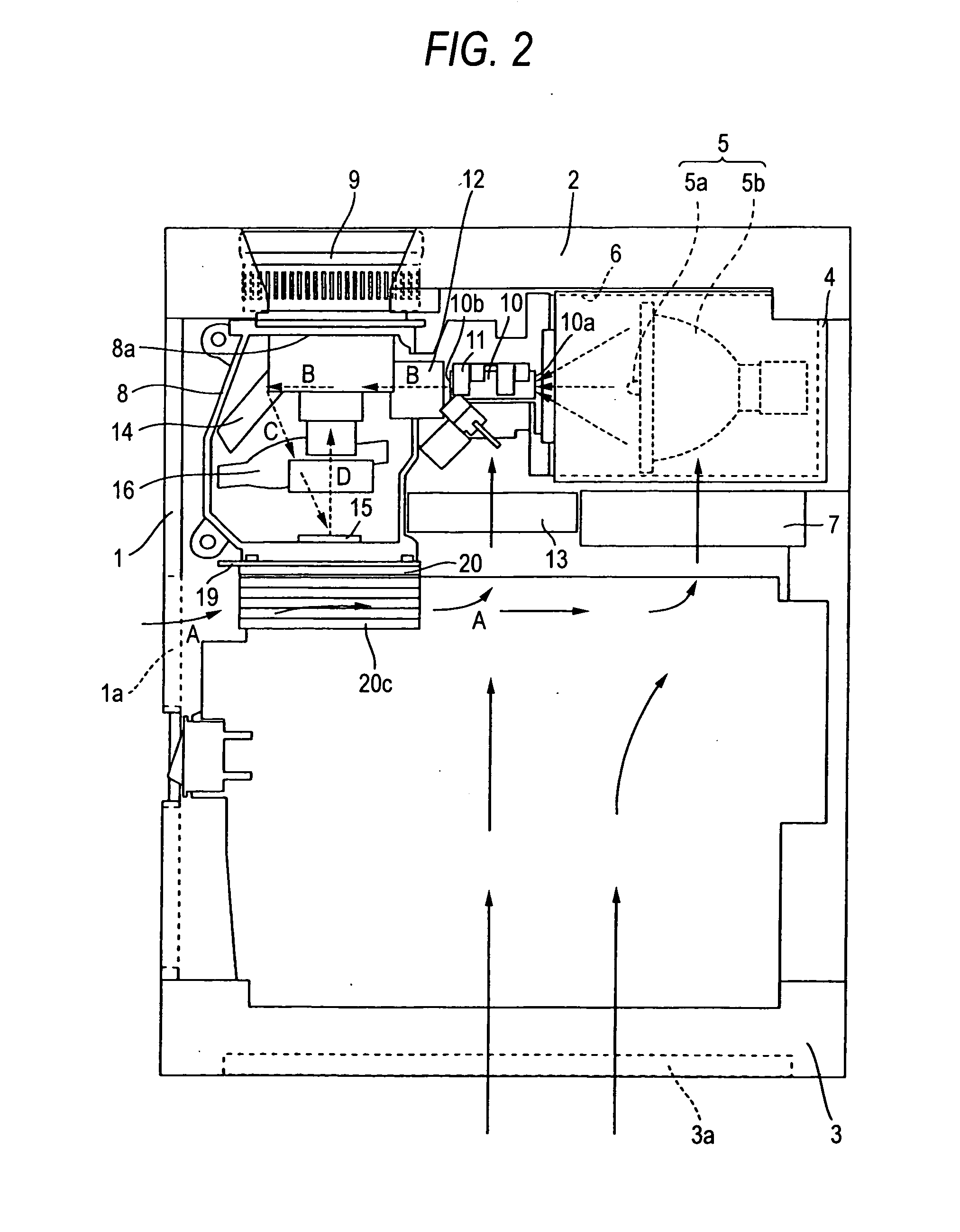
[0033]FIG. 1 is a perspective view illustrating an overall configuration of a projector in accordance with an embodiment of the invention. FIG. 2 is a top view of the projector in accordance with the embodiment shown in FIG. 1. FIG. 3 is a cross-sectional view for explaining a structure for attaching a DMD device and a heat radiating plate used in the projector in accordance with the embodiment shown in FIG. 1. FIG. 4 is a perspective view of the heat radiating plate used in the projector in accordance with the embodiment shown in FIG. 1. First, referring to FIGS. 1 to 4, a description will be given of the structure of the projector in accordance with the embodiment of the invention.

[0034] As shown in FIG. 1, a projector in accordance with an embodiment of the invention has a lower case 1, a front case 2, and a rear case 3. A ventilation port 1a for introducing air is pro...


PUM


Abstract

A projector includes a light source lamp, a projection lens, a DMD device, a temperature controlling fan, an optical part, a cooling fan, and a heat radiating plate. Preferably, the heat radiation plate is provided in a path to the fans and in close proximity to the DMD device, and includes a base portion and a plurality of heat radiating fin portions, which are provided integrally on a surface of the base portion, are spaced apart at predetermined intervals and extend in a perpendicular direction to the surface of the base portion. Each of the plurality of heat radiating fin portions has a plurality of through holes which extend in a direction along the path to the fans and are spaced apart at predetermined intervals. An outer surface of the heat radiating fin portion has a shape which reflects a shape of the plurality of through holes.

Description

BACKGROUND OF THE INVENTION [0001] 1. Field of the Invention [0002] The present invention relates to a projector, and more particularly to a projector including heat radiating fin portions for radiating heat generated during operation. [0003] 2. Description of the Related Art [0004] Conventionally, a projector including heat radiating fin portions for radiating heat generated during operation is known (e.g., refer to JP-A-2002-90886 and JP-A-2002-174795). [0005] The aforementioned JP-A-2002-90886 discloses a projector in which a heat radiating fin portion is formed on an outer surface of a color wheel case or accommodating a color wheel, whereby the heat generated from the color wheel rotating at high speed during the operation of the projector is radiated from the heat radiating fin portion. [0006] In addition, the aforementioned JP-A-2002-174795 discloses a projector in which a heat radiating plate having a heat radiating fin portion is provided in an abutting manner on a DMD devi...

Claims


Application Information

Patent Timeline
IPC IPC(8): G02B26/08G03B21/00G03B21/16G03B21/18
CPCG03B21/18
Inventor MORINAGA, KENICHI
Owner FUNAI ELECTRIC CO LTD
Why Eureka
Try Eureka