Method for fabrication of magnetic write head with self aligned poles

a technology of self-aligning poles and write heads, which is applied in the manufacture of head surfaces, magnetic recording, decorative arts, etc., can solve the problems of difficult alignment of two independently fabricated elements of such small magnitude, and achieve the reduction of the need for handling and fixation, and less dependence on photolithography. , the effect of increasing the consistency of production runs

Inactive Publication Date: 2005-03-31
HITACHI GLOBAL STORAGE TECH NETHERLANDS BV
View PDF3 Cites 1 Cited by
  • Summary
  • Abstract
  • Description
  • Claims
  • Application Information

AI Technical Summary

Benefits of technology

[0009] It is an advantage of the present invention that poles of very narrow dimension can be fabricated that will be aligned without the problems associated with aligning two elements of such tiny dimensions.
[0010] It is a further advantage of the present invention that by self-aligning the poles, the need for handling and fixturing is reduced compared to other methods by which the poles may be aligned.
[0011] It is another advantage of the present invention that the invention requires less dependency on photolithography which will increase consistency in production runs.
[0012] It is yet another advantage of the present invention that it can be practiced with existing production equipment and techniques.

Problems solved by technology

Thus, there is the difficulty of aligning two components whose dimensions may be on the order of 0.4 μm (0.4×10⁻⁶ meters) in width.
Obviously, aligning two independently fabricated elements of such small magnitude would be a difficult task, and it would be much preferable to have the poles “self-aligned” or fabricated in proper registration with each other to begin with.

Method used


Image

  • Method for fabrication of magnetic write head with self aligned poles
  • Method for fabrication of magnetic write head with self aligned poles
  • Method for fabrication of magnetic write head with self aligned poles

Examples


Embodiment Construction

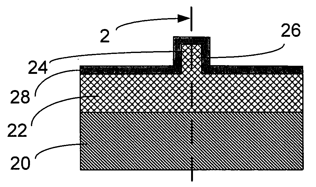
[0027] Please note that dimensions discussed below are not to be construed as limitations, but are merely representative of preferred dimensions. Many variations in dimensions are possible as will be obvious to one skilled in the art, and all are contemplated by the present invention. Also please note that no attempt has been made to draw the layers and structures to accurate scale, and relative thicknesses of layers are not meant to be in true proportions or construed as limitations on relative dimensions of elements.

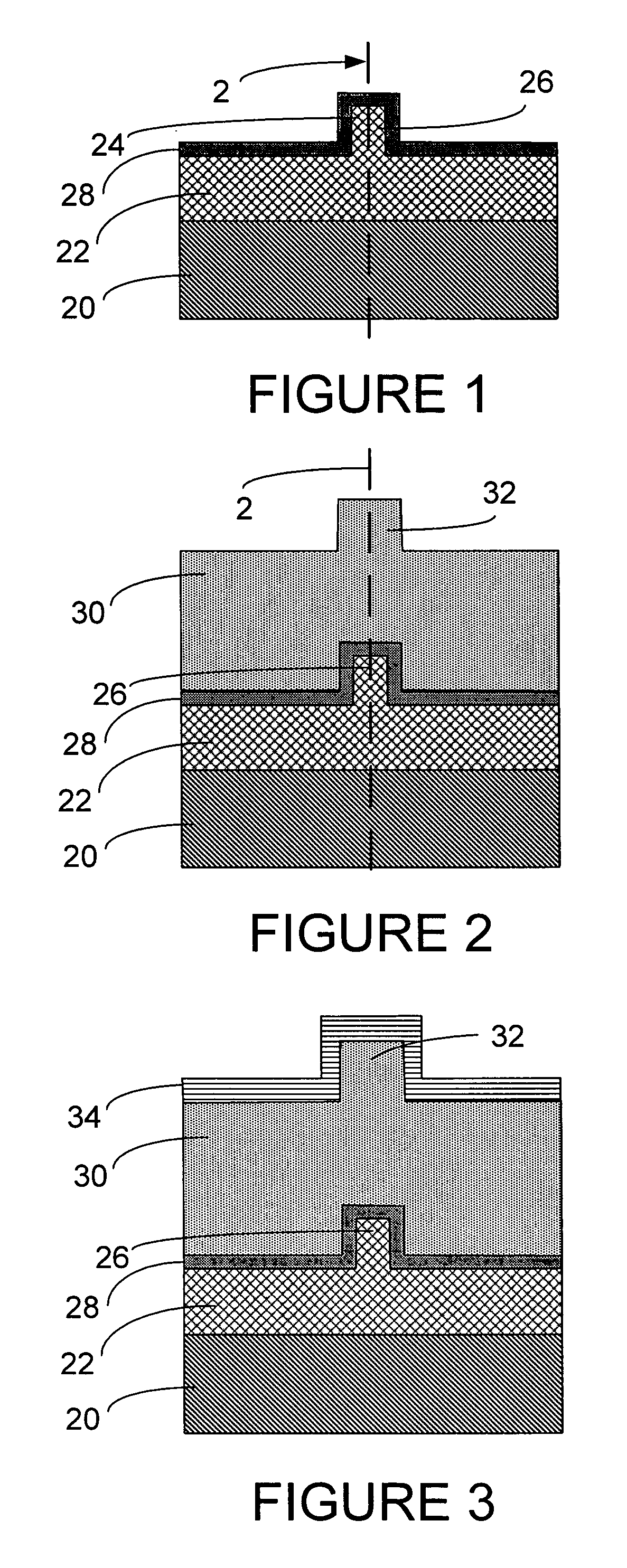
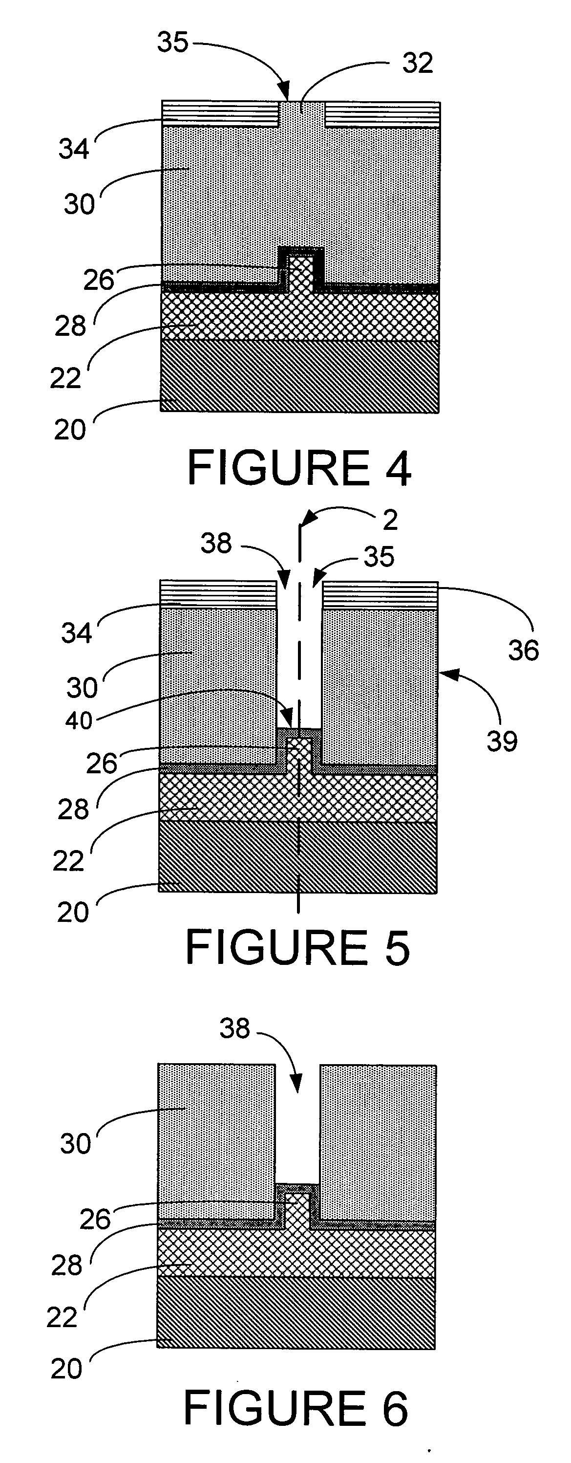
[0028] The following discussion refers to all FIGS. 1-12 generally.

[0029] As seen in FIG. 1, the P1 Protrusion 26, which shall alternately be referred to as PIP 26 is formed by first forming the P1 layer 20, preferably formed from CoFe, NiFe, CoFeN, or CoNiFe, and then plating the N3 layer 22, which is also high magnetic-moment material such as CoFe, NiFe, CoFeN, and CoNiFe. The N3 layer 22 then undergoes CMP (Chemical Mechanical Polishing). The PIP layer 24 is then ...


PUM

PropertyMeasurementUnit
widthaaaaaaaaaa
heightaaaaaaaaaa
depthaaaaaaaaaa

Abstract

A method for fabrication of magnetic write heads for disk drives in which a P1 layer is formed having a P1 Protrusion, the P1 Protrusion having a longitudinal reference axis. A gap layer is deposited on the P1 Protrusion and a layer of fill material is deposited on the gap layer. The fill material layer is shaped to form a mold which surrounds a hollow which is aligned with the longitudinal axis of the P1 Protrusion. This hollow in the fill material layer is filled with P2 pole material to form a P2 pole which is then automatically substantially aligned with the longitudinal axis of the P1 Protrusion.

Description

BACKGROUND OF THE INVENTION [0001] 1. Field of the Invention [0002] The present invention relates generally to manufacture of heads for data storage devices and more specifically to a write head with first and second pole tips which are self aligned during the manufacturing process. [0003] 2. Description of the Prior Art [0004] A computer disk drive stores and retrieves data by positioning a magnetic read / write head over a rotating magnetic data storage disk. The head, or heads, which are typically arranged in stacks, read from or write data to concentric data tracks defined on surface of the disks which are also typically arranged in stacks. The heads are included in structures called “sliders” into which the read / write sensors are imbedded during fabrication. The goal in recent years is to increase the amount of data that can be stored on each hard disk. If data tracks can be made narrower, more tracks will fit on a disk surface, and more data can be stored on a given disk. The wi...

Claims


Application Information

Patent Timeline
Patent Type & Authority Applications(United States)
IPC IPC(8): B44C1/22G11B5/187G11B5/23G11B5/31
CPCG11B5/187G11B5/232Y10T29/49043G11B5/3163Y10T29/49046G11B5/3116
Inventor BERGEVIN, CHRISTOPHER W.JARRATT, JAMES D.LO, JYH-SHUEY JERRYZHANG, SUE SIYANG
Owner HITACHI GLOBAL STORAGE TECH NETHERLANDS BV
Why Eureka
Try Eureka