Fluidized bed reactor system having an exhaust gas plenum

a technology of fluidized bed and reactor system, which is applied in the direction of lighting and heating apparatus, combustion types, furnaces, etc., can solve the problems of inability to recover heat energy from exhaust gases, heavy refractory-lined ducts, and ducts that require regular maintenan

Inactive Publication Date: 2005-05-26
FOSTER WHEELER ENERGY CORP
View PDF7 Cites 13 Cited by
  • Summary
  • Abstract
  • Description
  • Claims
  • Application Information

AI Technical Summary

Benefits of technology

[0028] Since the gas plenum is integrated with the reaction chamber, it may be formed in a s

Problems solved by technology

A disadvantage in this kind of arrangement is that erosion and temperature fluctuations cause wearing and embrittlement in the refractory-lined ducts, whereby the ducts require regular maintenance.
Furthermore, refractory-lined ducts are heavy and require additional support.
Since the ducts have no heat surfaces, it is not possible to recover heat energy from the exhaust gases therein.
A significant disadvantage in such a circulat

Method used


Image

  • Fluidized bed reactor system having an exhaust gas plenum
  • Fluidized bed reactor system having an exhaust gas plenum
  • Fluidized bed reactor system having an exhaust gas plenum

Examples


Embodiment Construction

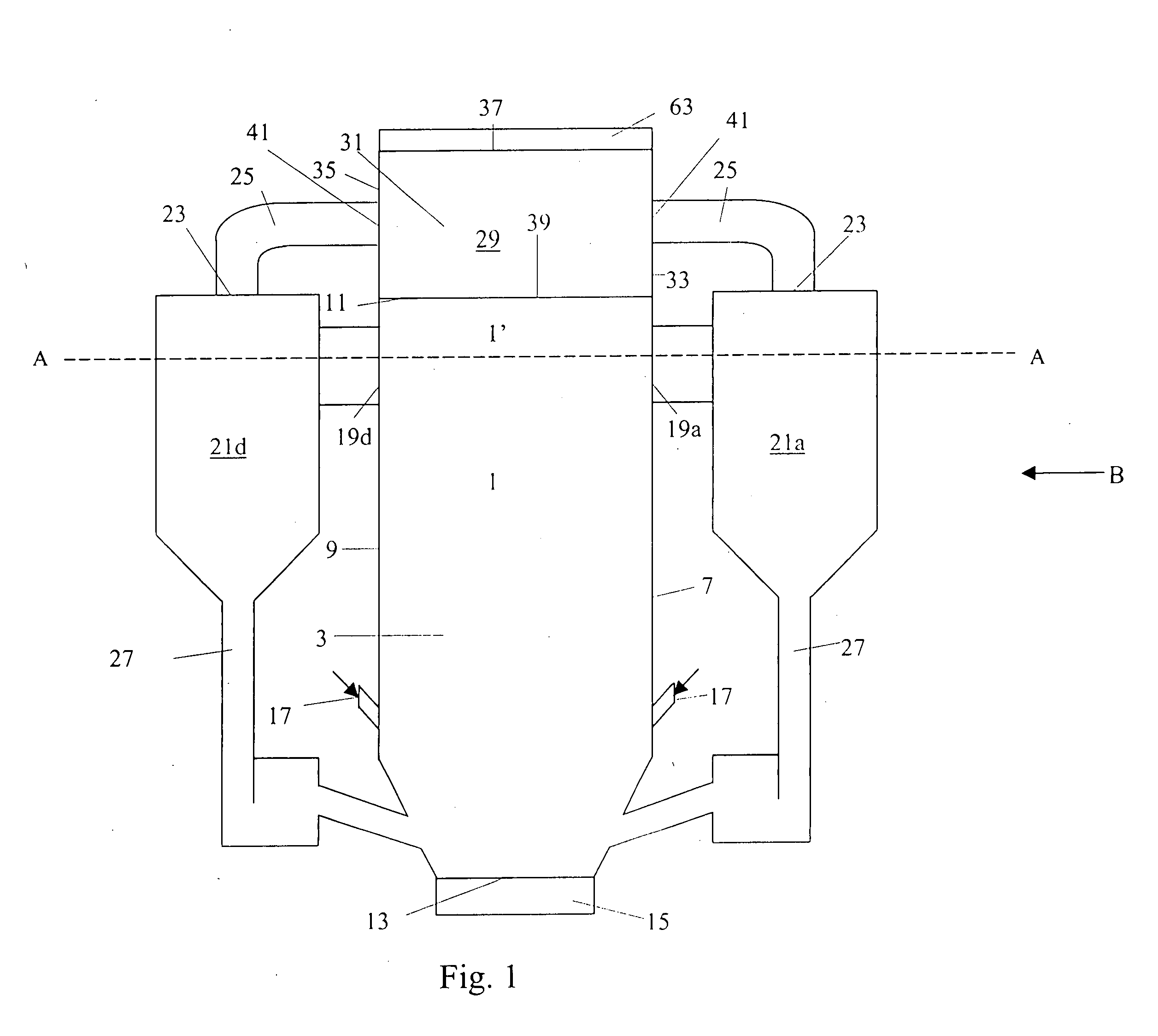
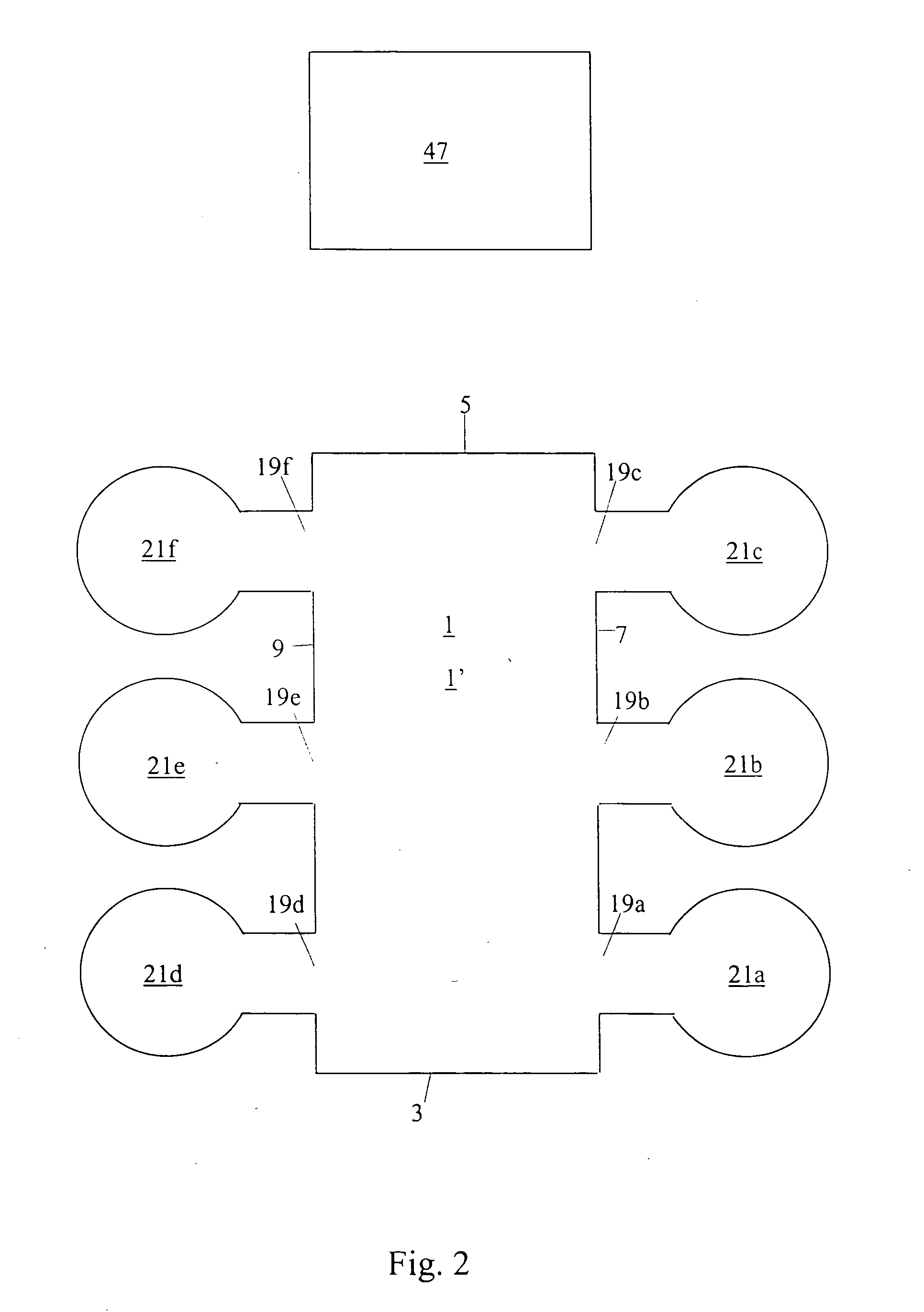
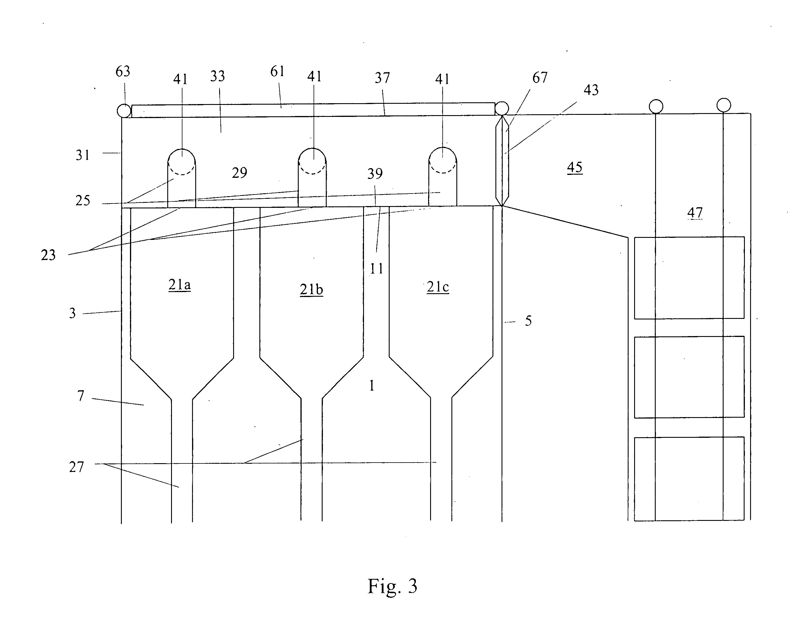
[0040] A circulating fluidized bed reactor system, as shown in FIGS. 1, 2, and 3, comprises a reaction chamber 1, having a fluidized bed of solid particles therein. The reaction chamber 1 is defined by a front wall 3, a rear wall 5, a right side wall 7 and a left side wall 9, a ceiling 11, and a bottom 13, of which chamber is formed by conventional water tube panels comprising water tubes joined by fins. The reaction chamber 1 comprises means 15 for introducing fluidizing gas, such as nozzles or airpipes, and means 17 for introducing fuel, such as pneumatic or gravimetric fuel feeders. The side walls 7, 9 of the reaction chamber are provided with six discharge openings 19a-19f for removing a particle suspension of exhaust gas and solid particles, formed in the reaction chamber 1, through an upper part 1′ of the reaction chamber 1. The discharge openings 19a-19f of the reaction chamber are respectively provided with six particle separators 21a-21f for separating the solid particles f...


PUM


Abstract

An arrangement for directing exhaust gases from at least one particle separator of a circulating fluidized bed reactor system to a heat recovery section includes a gas plenum located above a reaction chamber, the gas plenum being defined by a ceiling, a bottom, and walls and being integrated with the reaction chamber. The walls of the gas plenum are provided with at least one inlet opening for cleaned exhaust gases, each of which is coupled with a discharge duct connected to one of the particle separators, for directing the cleaned exhaust gases from the particle separators to the gas plenum, from where the cleaned exhaust gases are directed to the heat recovery section downstream of the gas plenum. The reaction chamber is at least partially formed by water tube panels, and the enclosure of the gas plenum is also formed by water tube panels as extensions of water tube panels of the reaction chamber.

Description

BACKGROUND OF THE INVENTION [0001] 1. Field of the Invention [0002] This invention relates to an arrangement in a circulating fluidized bed reactor system for directing exhaust gases from at least one particle separator to a heat recovery section. [0003] 2. Description of the Related Art [0004] The circulating fluidized bed reactor system comprises a reaction chamber, having a fluidized bed of solid particles therein and a particle suspension of exhaust gases and solid particles being discharged through at least one discharge opening arranged in the upper part thereof. Each discharge opening is connected to a particle separator for separating the solid particles from the particle suspension. The upper part of each particle separator is provided with a gas discharge opening for the discharge of cleaned exhaust gas flow. The cleaned exhaust gases are directed from the particle separators to a heat recovery section of the circulating fluidized bed reactor system. Each particle separato...

Claims


Application Information

Patent Timeline
IPC IPC(8): F22B31/00F23C10/10F23M5/08
CPCF22B31/003F23M5/08F23C10/10F22B31/0084B01J8/18F23C10/00F23M5/00F22B31/00
Inventor DARLING, SCOTT
Owner FOSTER WHEELER ENERGY CORP
Why Eureka
Try Eureka