Scan bar and method for scanning an image

a scanning bar and image technology, applied in the field of scanners, can solve the problems of small and more expensive sensor elements that must be used, and achieve the effects of improving scanner resolution, scanning resolution, and scanning resolution

Active Publication Date: 2005-06-09
LEXMARK INT INC
View PDF15 Cites 26 Cited by
  • Summary
  • Abstract
  • Description
  • Claims
  • Application Information

AI Technical Summary

Benefits of technology

[0006] Several benefits and advantages are derived from the broad method and / or the embodiment of the invention. By performing any image scanning used to create the final scanned image by using at least one linear sensor array which is not perpendicular to the subscan axis, a greater number of sensor elements will scan the image thereby increasing scanning resolution. A tilt angle of thirty degrees improves scanner resolution by approximately fifteen percent, and a tilt angle of forty-five degrees improves scanner resolution by approximately thirty percent.

Problems solved by technology

To increase resolution of the scanned image in this example, smaller and more expensive sensor elements must be used.

Method used


Image

  • Scan bar and method for scanning an image
  • Scan bar and method for scanning an image

Examples


Embodiment Construction

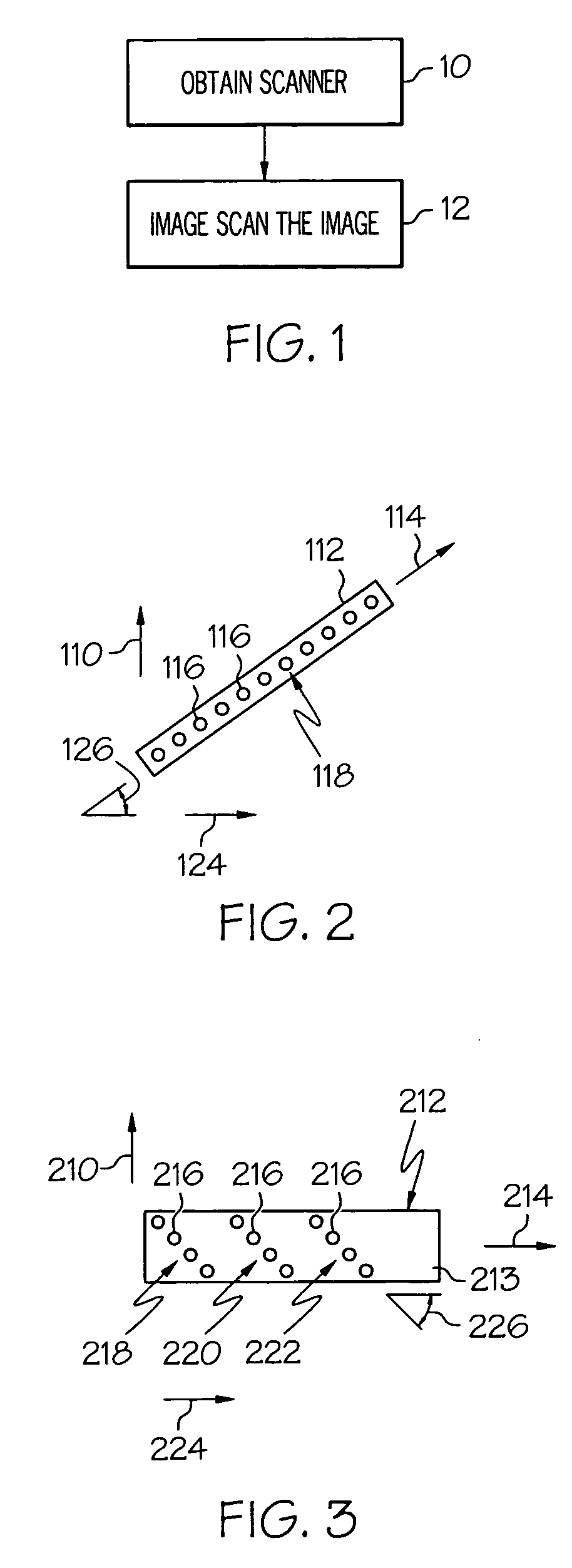
[0010]FIGS. 1-2 illustrate a first method of the invention which is for scanning an image and includes steps a) and b). Step a) is labeled as “Obtain Scanner” in block 10 of FIG. 1. Step a) includes obtaining a scanner having a subscan axis 110 and having a scan bar 112. The scan bar 112 includes a longitudinal axis 114 and includes a plurality of sensor elements 116 disposed in a substantially linear array 118 substantially along the longitudinal axis 114. The scan bar 112 is tilted with respect to a reference axis 124 at a substantially nonzero angle 126 which is fixed during any image scanning of the image used to create the final scanned image. The reference axis 124 lies substantially in a plane defined by the subscan axis 110 and the longitudinal axis 114, and the reference axis 124 is substantially perpendicular to the subscan axis 110. Step b) is labeled as “Image Scan The Image” in block 12 of FIG. 1. Step b) includes image scanning the image by relatively moving the scan b...


PUM


Abstract

A scanner is obtained having a subscan axis and having a scan bar including sensor elements positioned in at least one substantially linear array. Each array lies substantially in a plane defined by the subscan and scan-bar longitudinal axes. Each array is tilted with respect to a reference axis at a substantially nonzero angle which is fixed during any image scanning of the image used to create the final scanned image. The reference axis lies in the plane and is substantially perpendicular to the subscan axis. Image scanning the image is performed by relatively moving the scan bar over the image along the subscan axis. One embodiment of the scan bar includes a scan bar body and includes sensor elements supported by the scan bar body and positioned substantially in a common plane in multiple substantially linear arrays, wherein each array is tilted with respect to the scan-bar longitudinal axis.

Description

TECHNICAL FIELD [0001] The present invention relates generally to scanners, and more particularly to a scan bar and a method for scanning an image. BACKGROUND OF THE INVENTION [0002] Scanners are used to scan an image to create a scanned image which can be displayed on a computer monitor, which can be used by a computer program, which can be printed, which can be faxed, etc. One conventional method for scanning an image uses a scanner having a scan bar, wherein the scan bar includes a linear array of sensor elements aligned with the longitudinal axis of the scan bar. In one variation, an image on a rectangular sheet of paper is imaged scanned by aligning the width axis of the paper with (or making it parallel to) the longitudinal axis of the scan bar and then moving the scan bar over the image along a subscan axis of the scanner wherein the subscan axis is perpendicular to the longitudinal axis of the scan bar. In another variation, the scan bar is stationary, and the width axis of ...

Claims


Application Information

Patent Timeline
Patent Type & Authority Applications(United States)
IPC IPC(8): H04N1/04H04N1/191H04N1/193
CPCH04N1/193H04N1/1932H04N1/1934
Inventor CUNNIGAN, STEPHENMURRAY
Owner LEXMARK INT INC
Why Eureka
Try Eureka