Mounting apparatus for circuit boards

Inactive Publication Date: 2005-06-16
HON HAI PRECISION IND CO LTD
View PDF13 Cites 8 Cited by
  • Summary
  • Abstract
  • Description
  • Claims
  • Application Information

AI Technical Summary

Benefits of technology

[0008] An object of the present invention is to provide a mounting

Problems solved by technology

This motherboard installation method substantially increases the time and the cost because of the complexity and difficulty of the assembled or the disassembled.
While this projection structure hastens and reduces the cost associate with in

Method used


Image

  • Mounting apparatus for circuit boards
  • Mounting apparatus for circuit boards
  • Mounting apparatus for circuit boards

Examples


Embodiment Construction

[0017] Reference will now be made to the drawings to describe the present invention in detail.

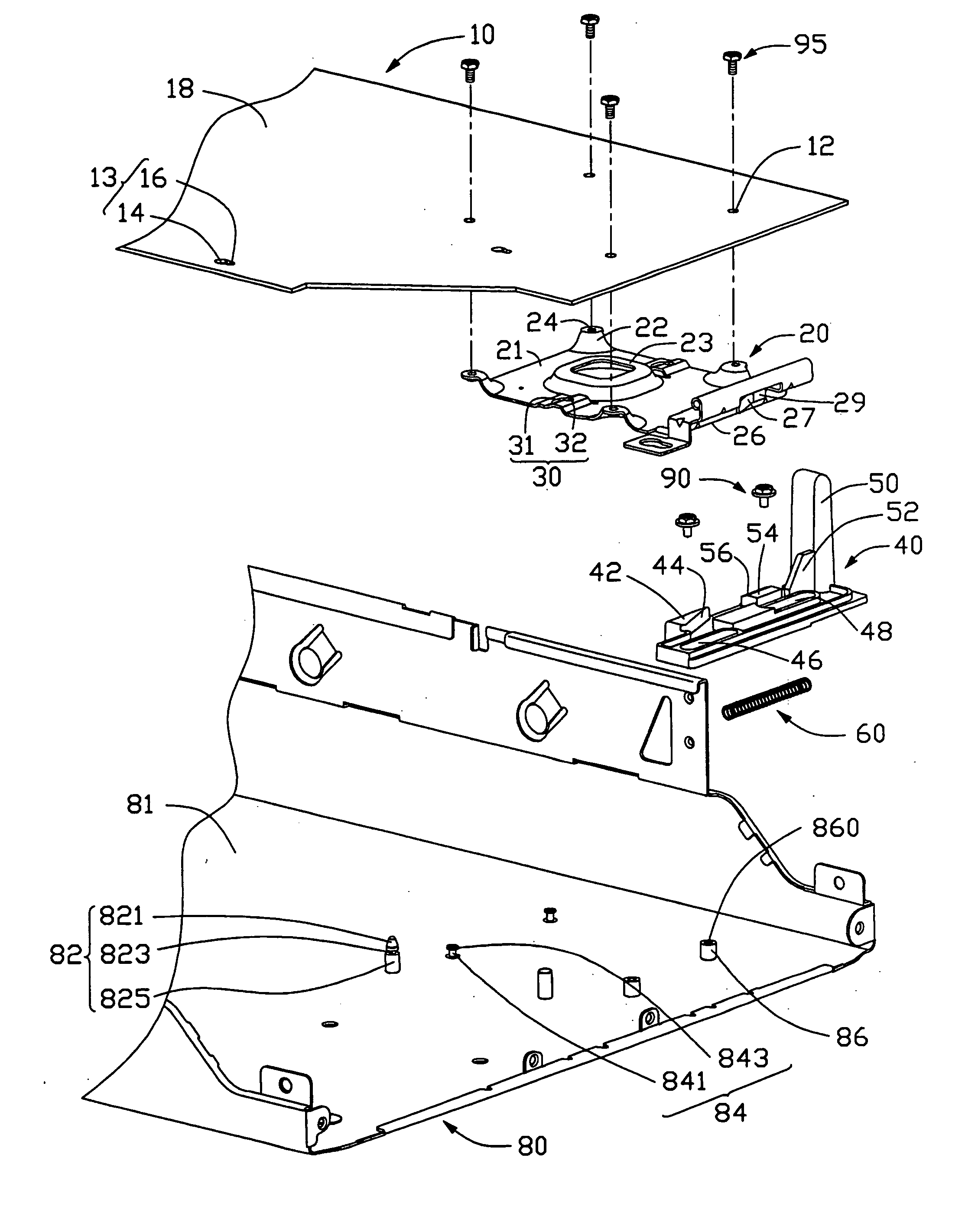
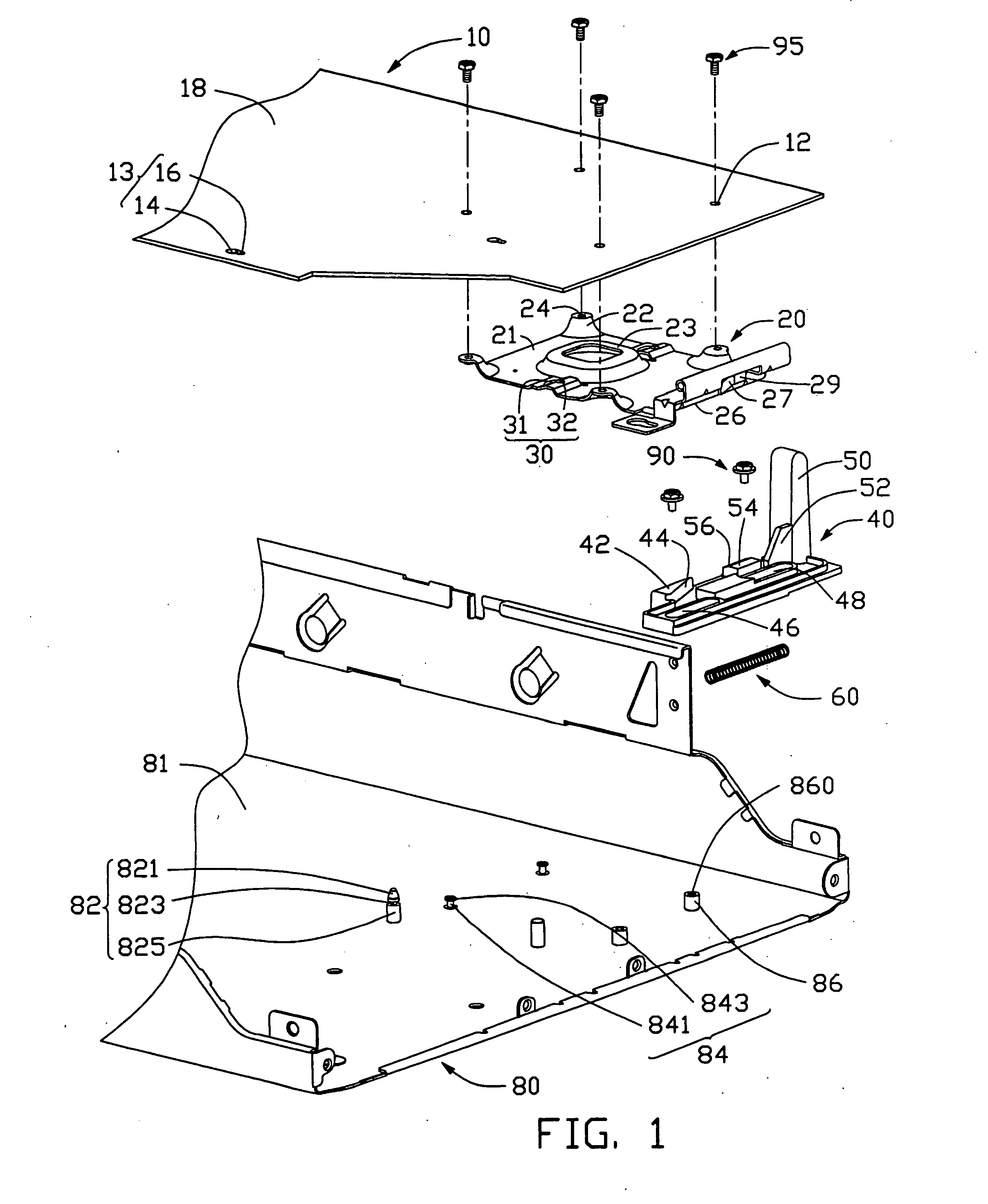
[0018]FIG. 1 shows a mounting apparatus in accordance with the preferred embodiment of the present invention, together with a circuit board such as a motherboard 10. The mounting apparatus comprises a supporting member 20, a fixing member 40, a coil spring 60 and a chassis 80.

[0019] The motherboard 10 is mounted to the chassis 80. The motherboard 10 has a generally planar, rectangular substrate body 18. The substrate body 18 defines several first mounting holes 13 therethrough, and four through holes 12 near an end thereof. Each first mounting hole 13 is generally calabash-shaped. The first mounting hole 13 has a first narrow portion 16, and a first broad portion 14.

[0020] The chassis 80 has a bottom wall 81. The bottom wall 81 has several upstanding first standoffs 82 corresponding to the first mounting holes 13 of the motherboard 10 respectively. Each standoff 82 includes cylindrical b...


PUM


Abstract

A mounting apparatus for mounting a motherboard (10) having several first mounting holes (13) includes a chassis (80), a fixing member (40), and a supporting member (20). The chassis comprised two posts (13) protruding from a bottom wall (81) thereof, and a number of standoffs (82) received in first the mounting hole. The fixing member is horizontally slidably mounted to the posts, and includes a first engaging portion (42) and a first locating portion (54). The supporting member is attached to the motherboard, and includes a second engaging portion (26) and a second locating portion (29). When the circuit board together with the supporting member is mounted to the chassis, the first locating portion engages with the second locating portion. When the circuit board together with the supporting member is disassembled from the chassis, the first engaging portion exerts force on the second engaging portion.

Description

BACKGROUND OF THE INVENTION [0001] 1. Field of the Invention [0002] The present invention relates to mounting apparatuses for circuit boards, and particularly to a mounting apparatus that readily attach a circuit board onto a computer chassis. [0003] 2. Description of Related Art [0004] For many years, the conventional method of installing a circuit board, such as a motherboard, in a computer was to simply screw the motherboard on a chassis of the computer. This motherboard installation method substantially increases the time and the cost because of the complexity and difficulty of the assembled or the disassembled. [0005] An improvement in the mounting of a motherboard in a computer is illustrated and described in U.S. Pat. No. 5,754,396. In this patent, the motherboard is mounted to a projection structure that can be slid into and out of a computer chassis to install and later remove the motherboard for access and service purpose. [0006] While this projection structure hastens and...

Claims


Application Information

Patent Timeline
IPC IPC(8): G06F1/18H05K7/14H05K7/18
CPCH05K7/1417G06F1/184
Inventor CHEN, YUN-LUNGGAO, XIAN-HUANG
Owner HON HAI PRECISION IND CO LTD
Why Eureka
Try Eureka