Metal stud punch system and a method of manufacture

Inactive Publication Date: 2006-02-16
KARIAKIN MR JOSEPH
View PDF15 Cites 0 Cited by
  • Summary
  • Abstract
  • Description
  • Claims
  • Application Information

AI Technical Summary

Benefits of technology

[0012] The present invention provides a system and method of modifying a standard C channel stud used in the manufacture of tilt-up style construction. By punching and forming a tab or series of tabs on one of the two parallel sides of the C channel, the tab bec

Problems solved by technology

For example, a stud edge surface in simple contact with the surface of the concrete panels results in a relatively weak bond and, therefore, a relatively weak panel.
The drawback with these cutouts in the studs is that common “C” channel must be either specially modified or specially manufactured which adds to the cost of labor and material of the finished panel.
The problem with this system is that the SteelCrete Punch Press is so large that it is prohibitive to take to the job site, because of the heavy Punch Press the studs have to be shipped twice.
This extra shipping and handling significantly raises costs.
Additionally, the higher cost of this press makes it not feasible for the smaller scale contractor.
Simple Building Systems, Inc. does supply pre-punched studs however, since the studs are specially modified or manufactured at an off-site manufacturing facility, the studs are not readily su

Method used


Image

  • Metal stud punch system and a method of manufacture
  • Metal stud punch system and a method of manufacture
  • Metal stud punch system and a method of manufacture

Examples


Embodiment Construction

[0022] Referring to the figures, like elements retain their indicators throughout the several views.

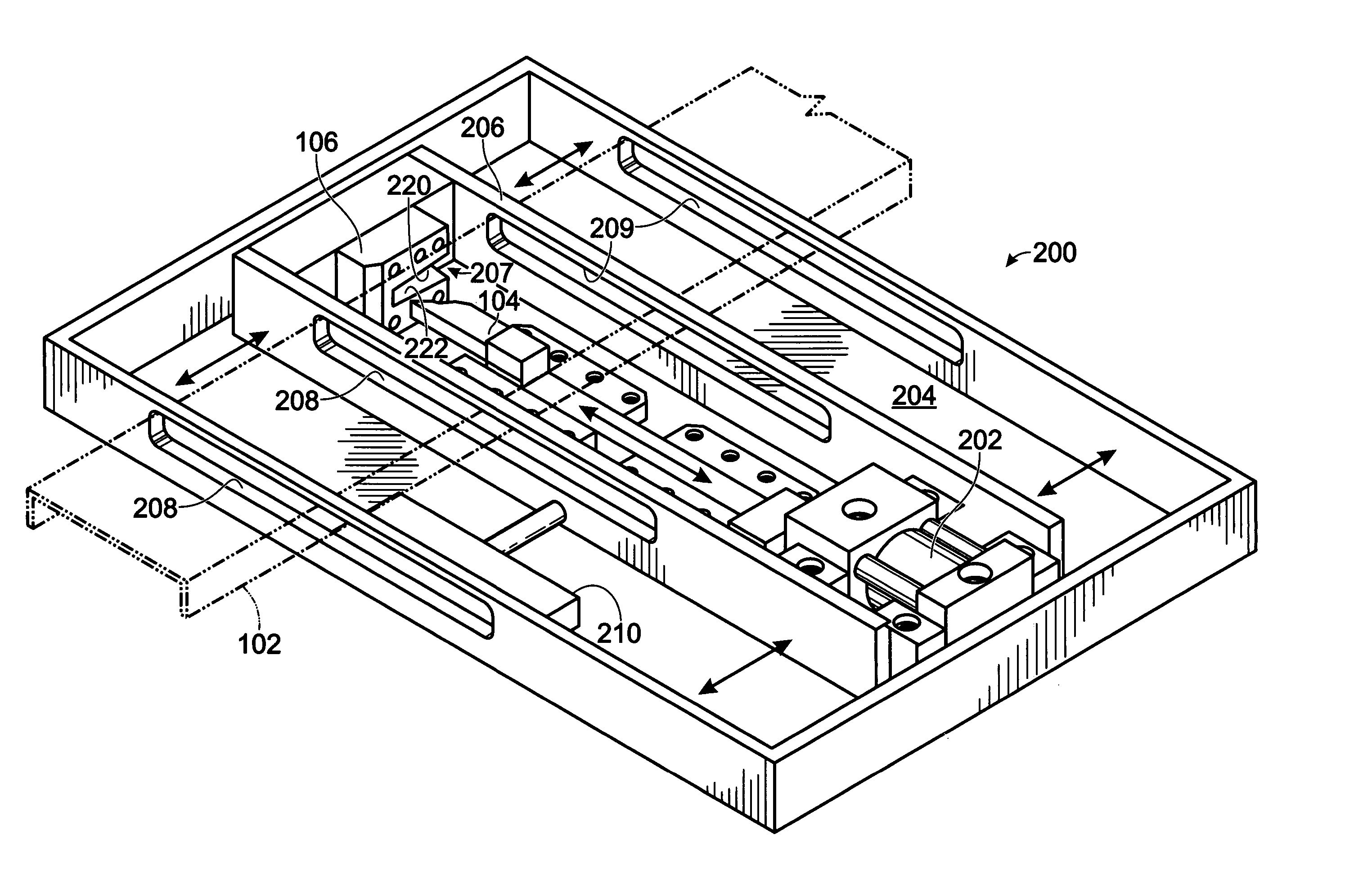
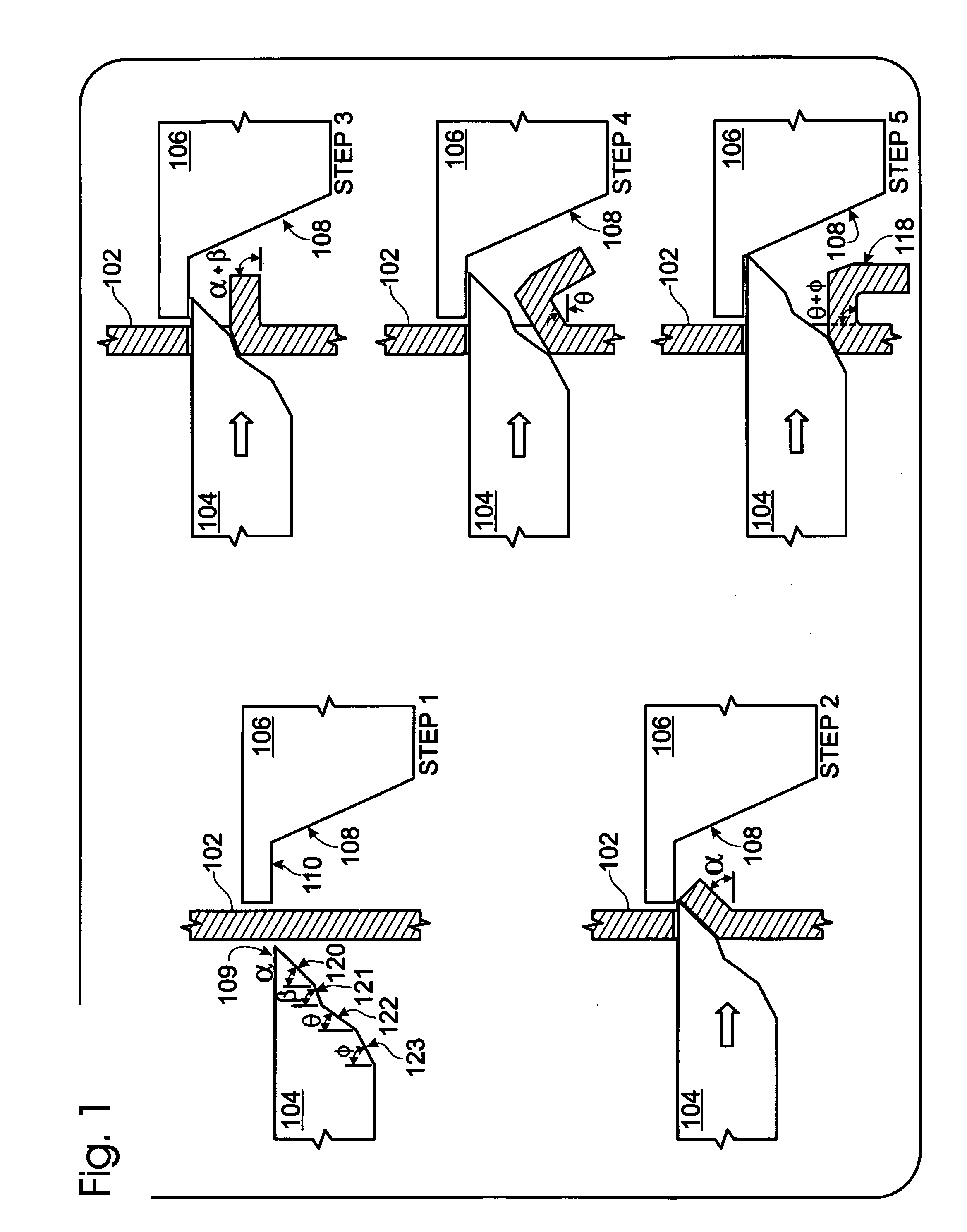
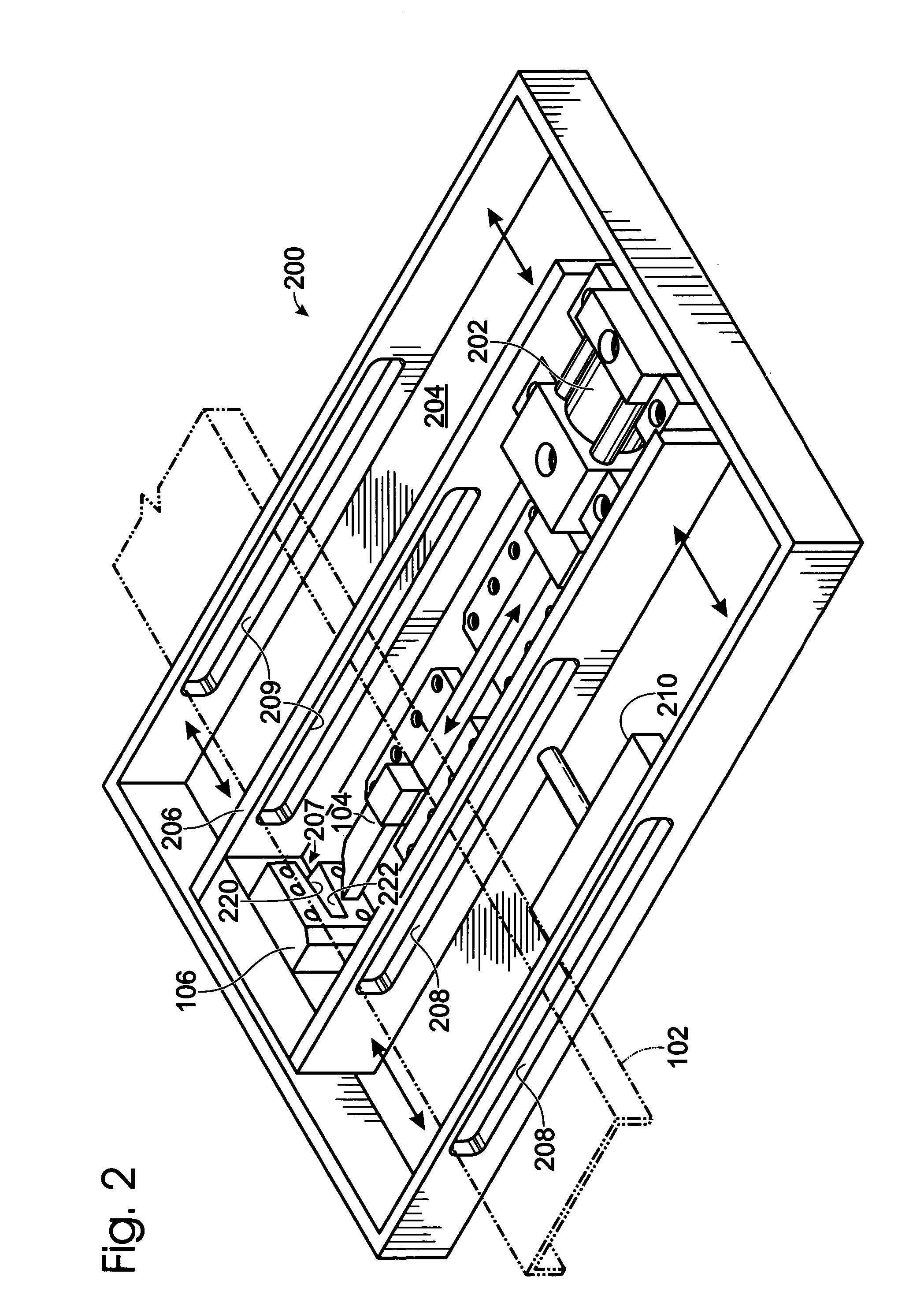
[0023]FIG. 1 is a cross-sectional view of Punch 104, Die 106, and Steel Stock 102 demonstrating the step-by-step punching and forming of Tab 118 on Steel Stock 102 according to the preferred embodiment of the present invention.

[0024] In the preferred embodiment of the present invention, Punch 104 is a four-staged punch. In Step 1, as is typical with most punch and die systems, Punch 104 has a Shear Edge 109 that is closely aligned with Die Shear Edge 110 thereby minimizing the deflection of Steel Stock 102 and making a clean cut into Steel Stock 102. In Step 2, as Punch 104 punches into Steel Stock 102, First Surface 120 of Punch 104 deforms Steel Stock 102 by an angle Alpha (a). In Step 3, Punch 104 continues toward Die 106 and Second Surface 121 deforms Steel Stock 102 by an angle Beta (β). In order to create an approximate 90 degree angle, Alpha and Beta sum to approximately 90 d...


PUM

PropertyMeasurementUnit
Lengthaaaaaaaaaa
Angleaaaaaaaaaa
Distanceaaaaaaaaaa

Abstract

A portable metal stud punching system has an alignment frame with an infeed alignment port in a first side and an outfeed alignment port in an opposite side. There is a punch and die positioned within the alignment frame. A length of metal stud is inserted through the infeed alignment port with one vertical side of the metal stud disposed between the punch and the die. A first hydraulic unit is attached to the punch and moves a first direction thereby inserting the punch into the die and punching a tab out of the vertical side of the metal stud. A second hydraulic unit moves the punch assembly in a direction perpendicular to the first direction of the first hydraulic unit. After the tab has been punched, the second hydraulic unit advances the metal stud by sliding the punch assembly a distance equal to the desired space between tabs. The punch is retracted by the first hydraulic unit and the punch assembly is returned to its original position by the second hydraulic unit.

Description

FIELD OF THE INVENTION [0001] This invention relates generally to building construction, and more particularly to the construction of and method of manufacturing tabbed structural members for tilt-up style wall construction. BACKGROUND OF THE INVENTION [0002] Tilt-up building construction is well known in the construction industry. Tilt-up thin-shell construction is a method of construction where the walls or panels are formed horizontally on a building slab or foundation from light gauge metal framing embedded in thin (1.5″ to 2″) concrete. Thin-shell construction is distinguished from traditional tilt-up construction which uses steel rebar inside of 6″ to 8″ thick concrete walls, rather than thinner concrete with external steel. There are obvious advantages to the newer thin-shell systems in material savings and ease of transporting and handling lighter panels. When the panels are dried and finished they are simply tilted up to become vertical walls. [0003] Another method employs ...

Claims


Application Information

Patent Timeline
IPC IPC(8): B21D28/02
CPCB21D28/243B21D28/10
Inventor KARIAKIN, JOSEPHROTH, AARON DAVIDTAYLOR, ROBERT BROOKS
Owner KARIAKIN MR JOSEPH
Why Eureka
Try Eureka