Restricting member and railcar including restricting member

Active Publication Date: 2017-05-11
KAWASAKI RAILCAR MFG CO LTD
View PDF1 Cites 2 Cited by
  • Summary
  • Abstract
  • Description
  • Claims
  • Application Information

AI Technical Summary

Benefits of technology

[0014]According to this configuration, the temporary fastening portion formed at the base portion is temporarily fastened to the temporary fastened portion formed at the side surface of the center pin. With this, the restricting member can be temporarily fastened to the center pin. In a state where the weight of the restricting member is supported by the center pin, for example, the restricting member can be attached to the center pin by a bolt. Therefore, an operator or the like can easily attach the restricting member to the center pin provided at the carbody. Further, even when the bolt is removed from the restricting member from a state where the restricting member is attached to the center pin b

Problems solved by technology

However, the air spring may cause abnormal rising, that is, the internal pressure of the air spring may increase by,

Method used


Image

  • Restricting member and railcar including restricting member
  • Restricting member and railcar including restricting member
  • Restricting member and railcar including restricting member

Examples


embodiment 1

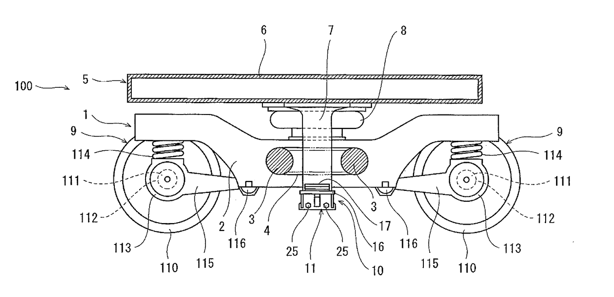
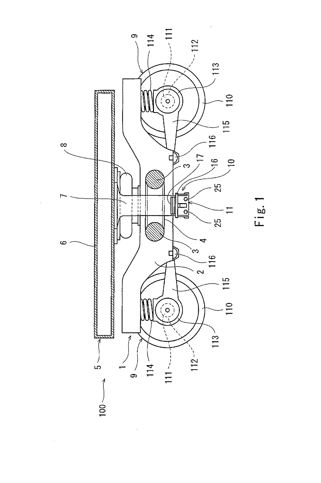
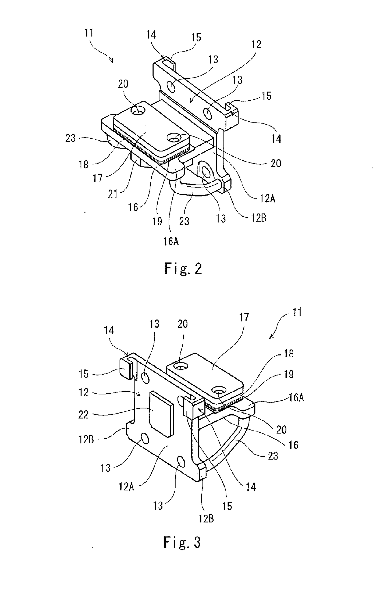
[0028]FIG. 2 is a perspective front view showing the restricting member 11 according to Embodiment 1 when viewed obliquely from above. FIG. 3 is a perspective rear view showing the restricting member 11 when viewed obliquely from above. As shown in FIGS. 2 and 3, the restricting member 11 of the present embodiment includes a base portion 12 and a contact portion 16. The contact portion 16 projects from the base portion 12 outward in the car width direction. When the air spring 8 expands by the predetermined amount or more, the contact portion 16 is brought into contact with the lower surface of the bogie frame 4 of the bogie 1 to restrict the abnormal rising of the carbody 5.

[0029]The base portion 12 is formed in a flat plate shape. The base portion 12 includes bolt holes 13 for fixing the base portion 12 to the center pin 7 by the fixing bolts 25. A resin member 17 is provided at a portion of the contact portion 16 so as to contact the bogie frame 4. Engineering plastic such as pol...

embodiment 2

[0045]FIG. 8 is a central longitudinal sectional view showing a height stopper 40 including a restricting member 41 according to Embodiment 2. In Embodiment 2, regarding components that are the same as the components of the restricting member 11 of the height stopper 10 of Embodiment 1, reference signs each obtained by adding “30” to the reference sign of the corresponding component of Embodiment 1 are used. In addition, regarding components that are the same as the components of the side surface 30 of Embodiment 1, reference signs each obtained by adding “30” to the reference sign of the corresponding component of Embodiment 1 are used. In FIG. 8, the handle portion 23 is not shown.

[0046]In the height stopper 40 including the restricting member 41 of Embodiment 2, a temporary fastening portion 44 of the restricting member 41 is provided at a rear surface of a base portion 42. The temporary fastening portion 44 is configured as a shaft portion 45 extending in a horizontal direction ...

embodiment 3

[0051]FIG. 9 is a central longitudinal sectional view showing a height stopper 70 according to Embodiment 3. In Embodiment 3, regarding components that are the same as the components of the restricting member 41 of the height stopper 40 of Embodiment 2, reference signs each obtained by adding “30” to the reference sign of the corresponding component of Embodiment 2 are used. In addition, regarding components that are the same as the components of the side surface 60 of Embodiment 2, reference signs each obtained by adding “30” to the reference sign of the corresponding component of Embodiment 2 are used. In FIG. 9, the handle portion 23 is not shown.

[0052]In the height stopper 70 of Embodiment 3, a temporary fastening portion 74 of a restricting member 71 is provided at a rear surface of a base portion 72. The temporary fastening portion 74 includes: a shaft portion 75A projecting in the horizontal direction to a predetermined position inside the center pin 7; and a projecting porti...


PUM


Abstract

The present invention relates to a restricting member configured to restrict abnormal rising of a carbody when an air spring expands by a predetermined amount or more. The restricting member includes: a base portion; a contact portion provided at the base portion and configured to be brought into contact with a lower surface of a bogie frame when the air spring expands by the predetermined amount or more; and a temporary fastening portion formed at the base portion. The temporary fastening portion is configured to be attachable to and detachable from a temporary fastened portion formed at a side surface of a center pin extending downward from a carbody.

Description

BACKGROUND OF THE INVENTION[0001]1. Field of the Invention[0002]The present invention relates to a restricting member configured to restrict abnormal rising of an air spring in a railcar and a railcar including the restricting member.[0003]2. Description of the Related Art[0004]Conventionally, in railcars, an air spring is used as a buffer device provided between a bogie provided with wheels and a carbody provided at an upper portion of the bogie. The air spring can expand or contract in an upward / downward direction by supplying or discharging compressed air to or from an air chamber formed inside the air spring. In the railcars, for example, performed is an automatic level controlling operation of adjusting the pressure of the air in the air spring such that the height of the railcar is maintained within a certain range by utilizing the expansion and contraction of the air spring.[0005]However, the air spring may cause abnormal rising, that is, the internal pressure of the air spri...

Claims


Application Information

Patent Timeline
IPC IPC(8): B61F5/10
CPCB61F5/10
Inventor SAKAHIRA, MASAHIROISOMURA, KAZUOTOJO, TAKANORIIKEDA, SATOSHIMAEBA, TOMOHIDEHIKOSAKA, NAOKINARITA, TOMOHIRO
Owner KAWASAKI RAILCAR MFG CO LTD
Why Eureka
Try Eureka