Cooling system for sleeves that are fixed to a carrier plate

a cooling system and carrier plate technology, applied in the field of carrier plate cooling system, can solve the problems of severe cooling action decline, the area to be supplied with fluid at the sleeves is about four times as large as the available entry area for cooling fluid, and the known cooling system suffers serious disadvantages, etc., to achieve greater flow speed, reduce the throttle effect, and increase the effect of fluid turbulen

Active Publication Date: 2005-07-28
MHT MOLD & HOTRUNNER TECH
View PDF1 Cites 1 Cited by
  • Summary
  • Abstract
  • Description
  • Claims
  • Application Information

AI Technical Summary

Benefits of technology

[0012] An object of the present invention is to improve the known cooling system for cooling the sleeves secured to the carrier plate, in accordance with the features of the kind set forth in the opening part of this specification, in such a way that, with an increase in the fluid turbulence phenomena, while reducing the throttle effect, greater flow speeds, a lesser danger of contamination and a greater level of cooling effici

Problems solved by technology

Known cooling systems however suffer from serious disadvantages.
The area which is to be supplied with fluid at the sleeves is therefore disadvantageously about four times as great as the available entry area for the cooling fluid.
In the absence of turbulence however the cooling action also falls sever

Method used


Image

  • Cooling system for sleeves that are fixed to a carrier plate
  • Cooling system for sleeves that are fixed to a carrier plate
  • Cooling system for sleeves that are fixed to a carrier plate

Examples


Embodiment Construction

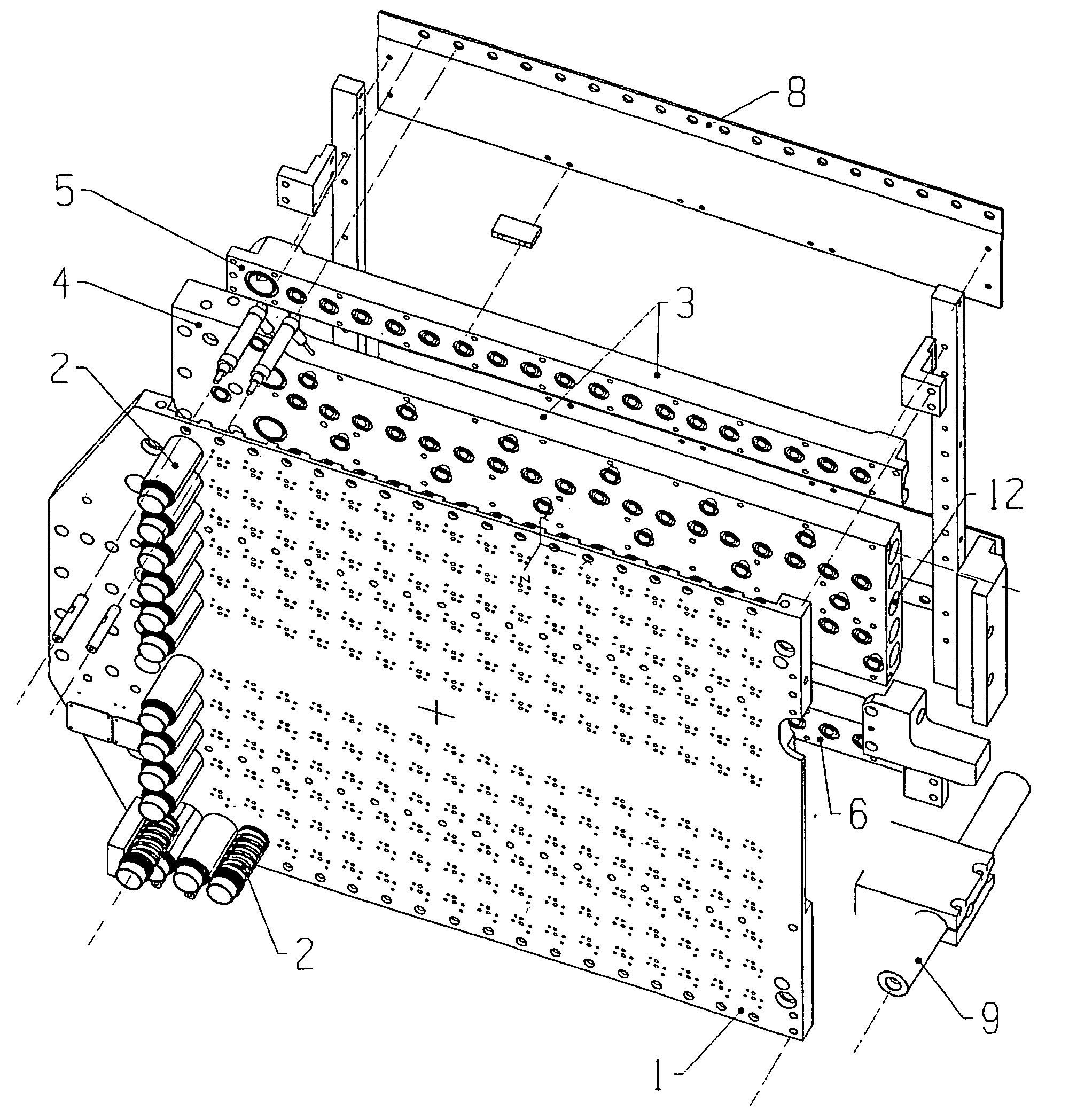
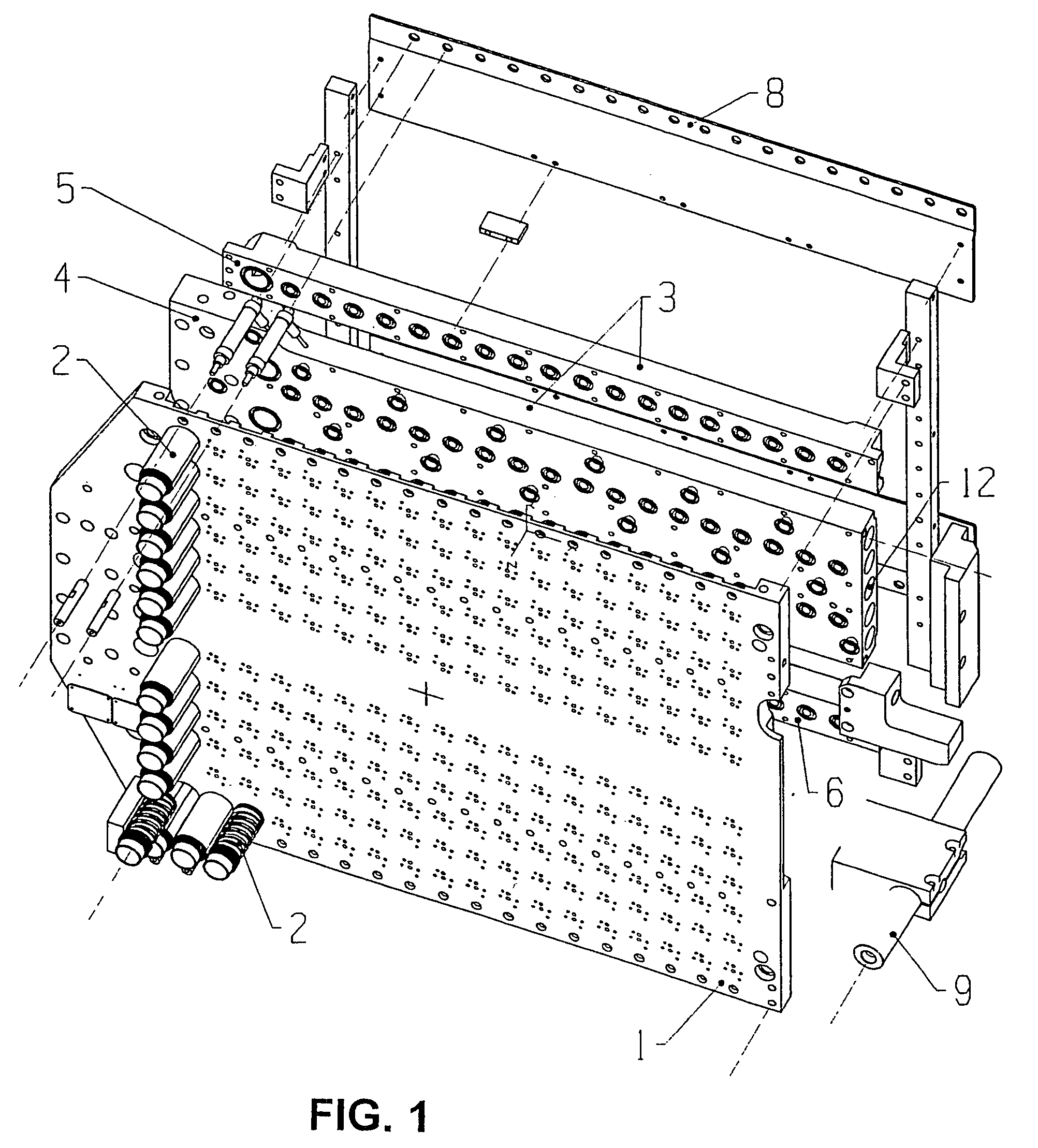
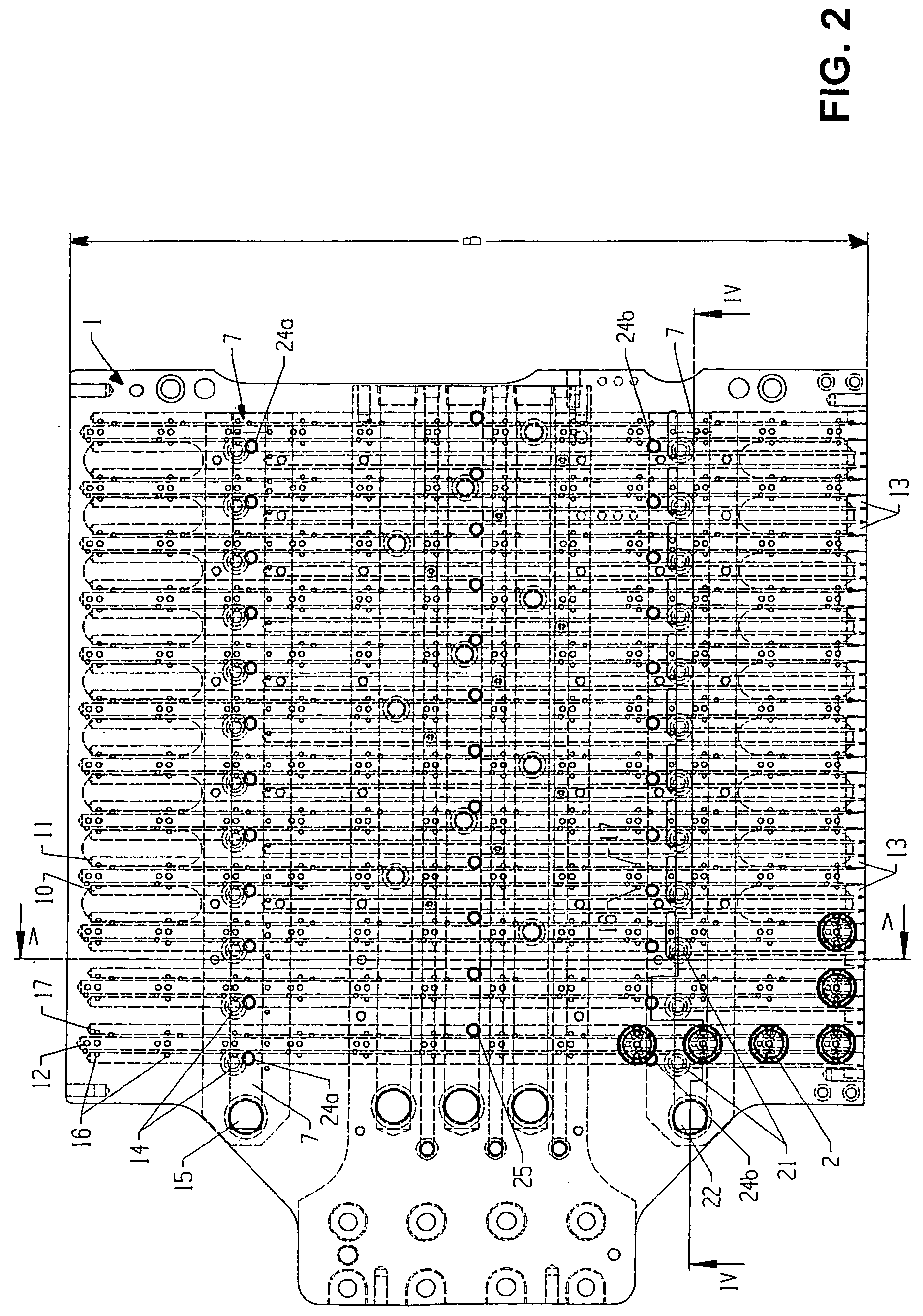
[0015] A block or barrier only needs to be provided at the location of the supply conduit, at which the fluid communication is to be interrupted, in order to make two supply conduits out of the one supply conduit, without the necessity for mechanical / physical changes in the structure of the carrier plate. By dividing the at least one supply conduit of the pair of supply conduits into two, the originally single flow path is subdivided into two sections for the flow pattern of that pair of supply conduits.

[0016] The sleeves (cooling sleeves) are arranged between the two supply conduits of a pair, which extend in mutually parallel relationship, in such a way that there is fluid communication from the one supply conduit by way of the sleeve to the other. That applies for all sleeves. In regard to the flow path for the fluid, this signifies that the fluid flows out of the one supply conduit by way of the sleeve into the other. In the known situation there is no interruption in the fluid...


PUM


Abstract

A cooling system for cooling sleeves (2) fixed to a carrier plate (1), by means of a fluid which is passed from a fluid inlet (15) to a fluid outlet (22) by way of fluid conduits (7, 14, 10, 11, 21) supported by means of the carrier plate (1). The fluid conduits (7, 14, 10, 11, 21) include main supply conduits (7) and supply conduits (10, 11) which extend approximately transversely with respect to each other. The supply conduits extend in a mutually parallel relationship and are arranged in pairs in the carrier plate (1) and are connected to a row of sleeves (2) by way of intake (16) and discharge conduits (17). The row of sleeves (2) is so disposed between the supply conduits (10, 11) of a pair such that each sleeve (2) is connected to both supply conduits (10, 11), and fluid communication is interrupted (plug 24) in at least the one supply conduit (10) of the pair substantially at the middle of its longitudinal extent (l).

Description

BACKGROUND OF THE INVENTION [0001] The invention concerns a cooling system for cooling sleeves fixed to a carrier plate, by means of a fluid which is passed from a fluid inlet to a fluid outlet by way of fluid conduits supported by means of the carrier plate, wherein belonging to the fluid conduits are main supply conduits and supply conduits which extend approximately transversely with respect thereto, the latter supply conduits extending in mutually parallel relationship and arranged in pairs in the carrier plate and being connected to a row of sleeves by way of intake and discharge conduits, wherein the row of sleeves is so disposed between the supply conduits of a pair that each sleeve is connected to both supply conduits. [0002] It is known for drinking water to be supplied to the end consumer in bottles comprising more or less transparent plastic material, in particular PET. As is known those PET bottles are blow-moulded from preforms which in turn are injection moulded from p...

Claims


Application Information

Patent Timeline
IPC IPC(8): B29C45/72
CPCB29C45/7207B29K2105/253B29C2045/725B29C2045/7214
Inventor LAUSENHAMMER, MANFREDTHOMMES, HELMUT
Owner MHT MOLD & HOTRUNNER TECH
Why Eureka
Try Eureka