Display device, liquid crystal monitor, liquid crystal television receiver, and display method

a technology of display device and display method, which is applied in the field of display device, can solve the problems of deterioration of gradation property, tn panel has a problem in its viewing angle property, and cannot completely eliminate the variation in gradation property, so as to achieve the effect of suppressing excess brightness

Inactive Publication Date: 2005-08-25
SHARP KK
View PDF17 Cites 76 Cited by
  • Summary
  • Abstract
  • Description
  • Claims
  • Application Information

AI Technical Summary

Benefits of technology

[0022] An embodiment of the present invention was made with the foregoing conventional problem in mind. Further, an object of an embodiment of the present invention is to provide a display device which can suppress the excess brightness.
[0042] Thus, it is possible to sufficiently reduce the brightness difference in at least a single sub-frame. On this account, an embodiment of the present display device can suppress the brightness difference as compared with the case of carrying out the normal hold display, so that it is possible to improve the viewing angle property. Thus, it is possible to favorably suppress the excess brightness.

Problems solved by technology

Incidentally, such a TN panel has a problem in its viewing angle property, as compared with a CRT.
However, even the VA panel which is thought to realize a wide viewing angle, cannot completely eliminate variation in the gradation property, due to variation in the viewing angle.
For example, the wider the viewing angle is in a horizontal direction, the more the gradation property is deteriorated.
That is, as illustrated in FIG. 2, when changing the viewing angle from 0° (front of the panel) to 60°, a gradation γ property accordingly varies, thereby causing such an excess brightness phenomenon that a luminance in halftone becomes excessively high.

Method used


Image

  • Display device, liquid crystal monitor, liquid crystal television receiver, and display method
  • Display device, liquid crystal monitor, liquid crystal television receiver, and display method
  • Display device, liquid crystal monitor, liquid crystal television receiver, and display method

Examples


Embodiment Construction

[0070] One embodiment of the present invention will be described below.

[0071] A liquid crystal display device (present display device) according to the present embodiment includes a liquid crystal panel that adopts the vertical alignment (VA) mode and that is divided into a plurality of domains.

[0072] The present display device serves as a liquid crystal monitor displaying an image based on an image signal, sent from outside, on the liquid crystal display panel.

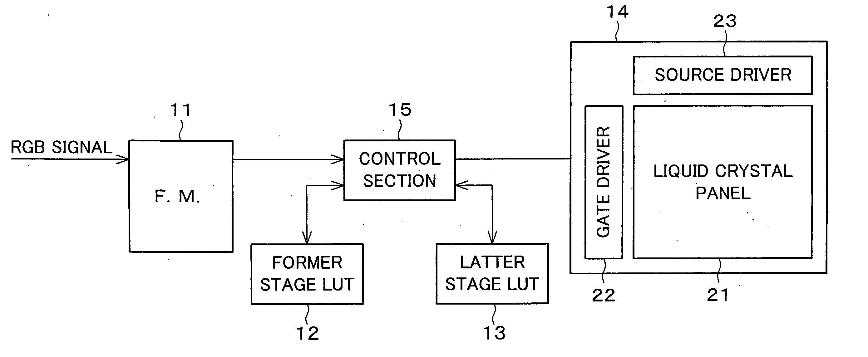
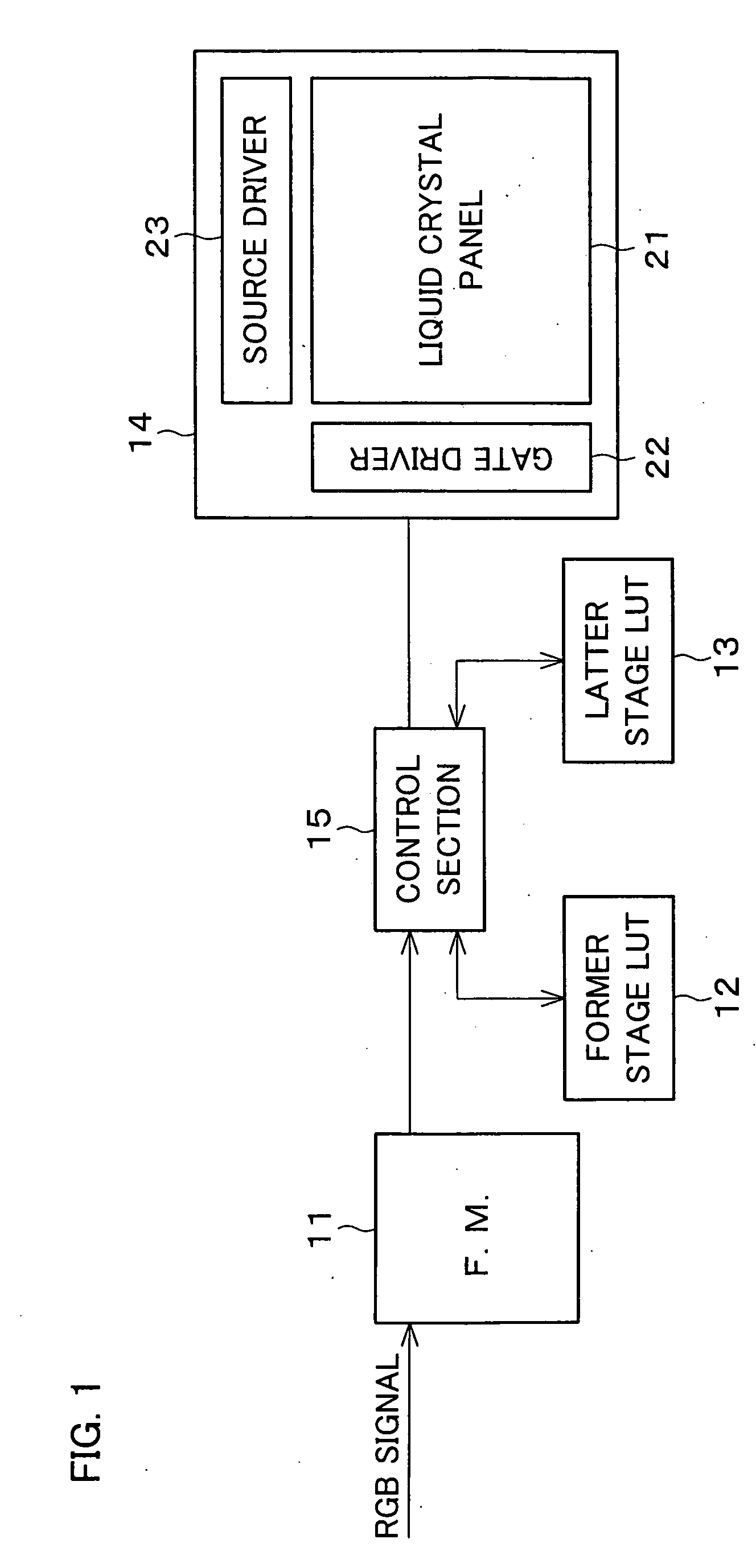
[0073]FIG. 1 is a block diagram illustrating an inside structure of the present display device.

[0074] As illustrated in FIG. 1, the present display device includes a frame memory (F.M.) 11, a former stage LUT 12, a latter stage LUT 13, a display section 14, and a control section 15.

[0075] The frame memory (image signal input section) 11 accumulates image signals (RGB signals), sent from an outer signal source, that correspond to a single frame.

[0076] Each of the former stage LUT (look-up table) 12 and the latter stage L...


PUM

PropertyMeasurementUnit
γaaaaaaaaaa
γaaaaaaaaaa
temperatureaaaaaaaaaa

Abstract

A control section divides a single frame so that a ratio of a period corresponding to a latter sub-frame and a period corresponding to a former sub-frame ranges from 1:3 to 1:7. A divisional point of the frame is a point which allows each of the latter sub-frame and the former sub-frame to minimize a difference between an actual brightness and an expected brightness. The frame may thus be divided at the point where the difference is largest in the normal hold display, so that it is possible to minimize the difference at this point. On this account, it is possible to reduce the difference in a single frame substantially by half as compared with an arrangement for carrying out the normal hold display, and thereby suppress the excess brightness caused by the difference.

Description

[0001] This Nonprovisional application claims priority under 35 U.S.C. § 119(a) on Patent Application No. 2004 / 013391 filed in Japan on Jan. 21, 2004 and on Patent Application No. 2005-12329 filed in Japan on Jan. 20, 2005, the entire contents of each of which are hereby incorporated herein by reference. FIELD OF THE INVENTION [0002] The present invention generally relates to a display device for displaying an image. Preferably, it relates to a display device displaying by using first and second sub-frames obtained by dividing a single frame. BACKGROUND OF THE INVENTION [0003] In recent years, a liquid crystal display device, particularly a color liquid crystal display device including a TN mode liquid crystal display panel (TN mode liquid crystal panel, TN panel), has come to be commonly used in a field where a CRT (Cathode Ray Tube) has been used. [0004] For example, document 1 (listed hereafter) discloses a liquid crystal display device that switches driving methods of a TN panel...

Claims


Application Information

Patent Timeline
Patent Type & Authority Applications(United States)
IPC IPC(8): G02F1/133G09G3/20G09G3/36G09G5/00H04N5/66
CPCG09G3/2029G09G3/2081G09G3/3611G09G3/3614G09G3/3648G09G2360/18G09G2300/0447G09G2300/0876G09G2320/0276G09G2320/028G09G2320/041G09G2300/0443G02F1/133G09G3/20G09G3/36
Inventor MIYATA, HIDEKAZUISHIHARA, TOMOYUKITOMIZAWA, KAZUNARI
Owner SHARP KK
Why Eureka
Try Eureka