Spacer for putting into place on a tubular element

Inactive Publication Date: 2005-09-01
GREMCO
View PDF10 Cites 12 Cited by
  • Summary
  • Abstract
  • Description
  • Claims
  • Application Information

AI Technical Summary

Benefits of technology

[0011] An object of the present invention is to devise a spacer of the type that can be threaded on a tubular element, the spac

Problems solved by technology

Nevertheless, such clip-on elements lead to dimensional problems insofar as it is necessary to have elements that are specific to each pipe or hose, which implies that special molding tools are required on each occasion.
Furthermore, the molded elements are generally relatively hard, and as a result the contact they make with a vibrating surface frequently generates banging or other undesirable noise.
This is done either by adhesive,

Method used


Image

  • Spacer for putting into place on a tubular element
  • Spacer for putting into place on a tubular element
  • Spacer for putting into place on a tubular element

Examples


Embodiment Construction

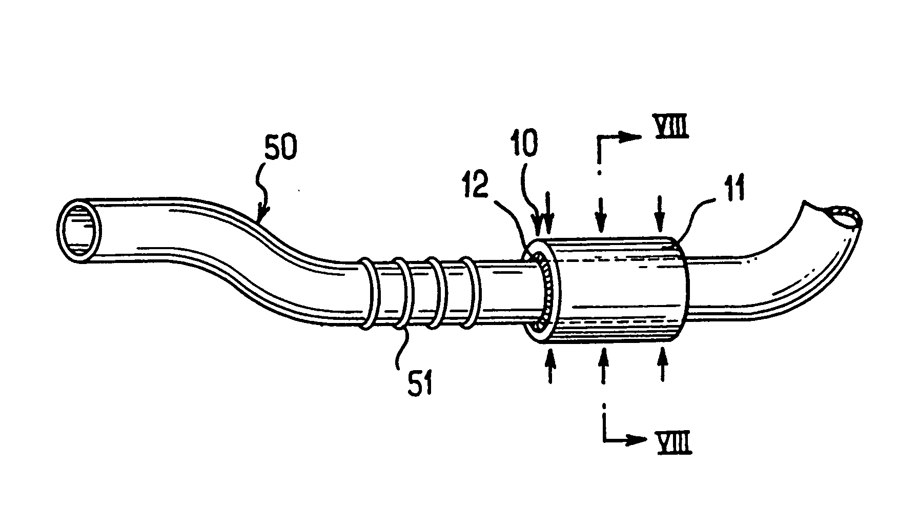
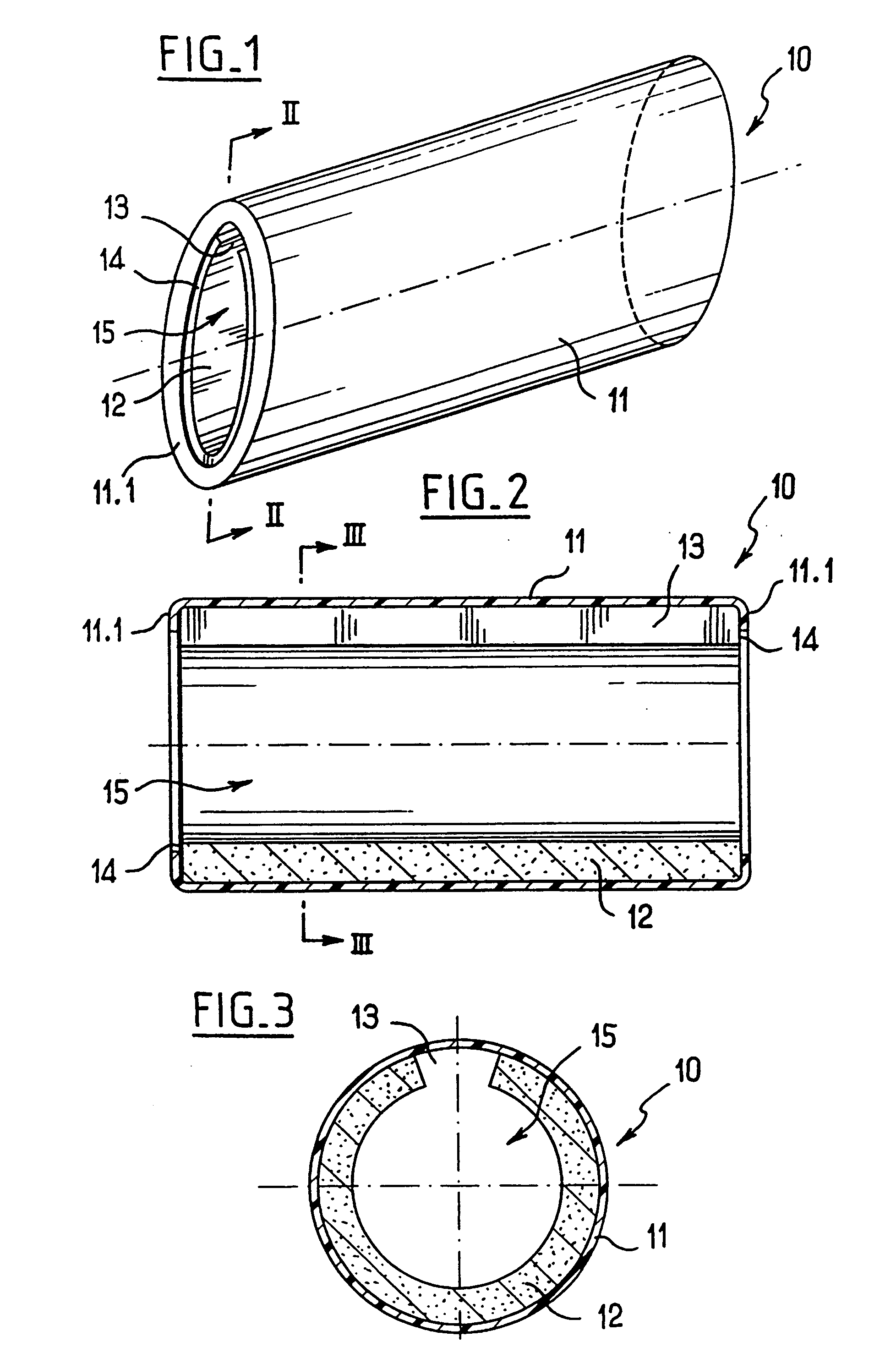
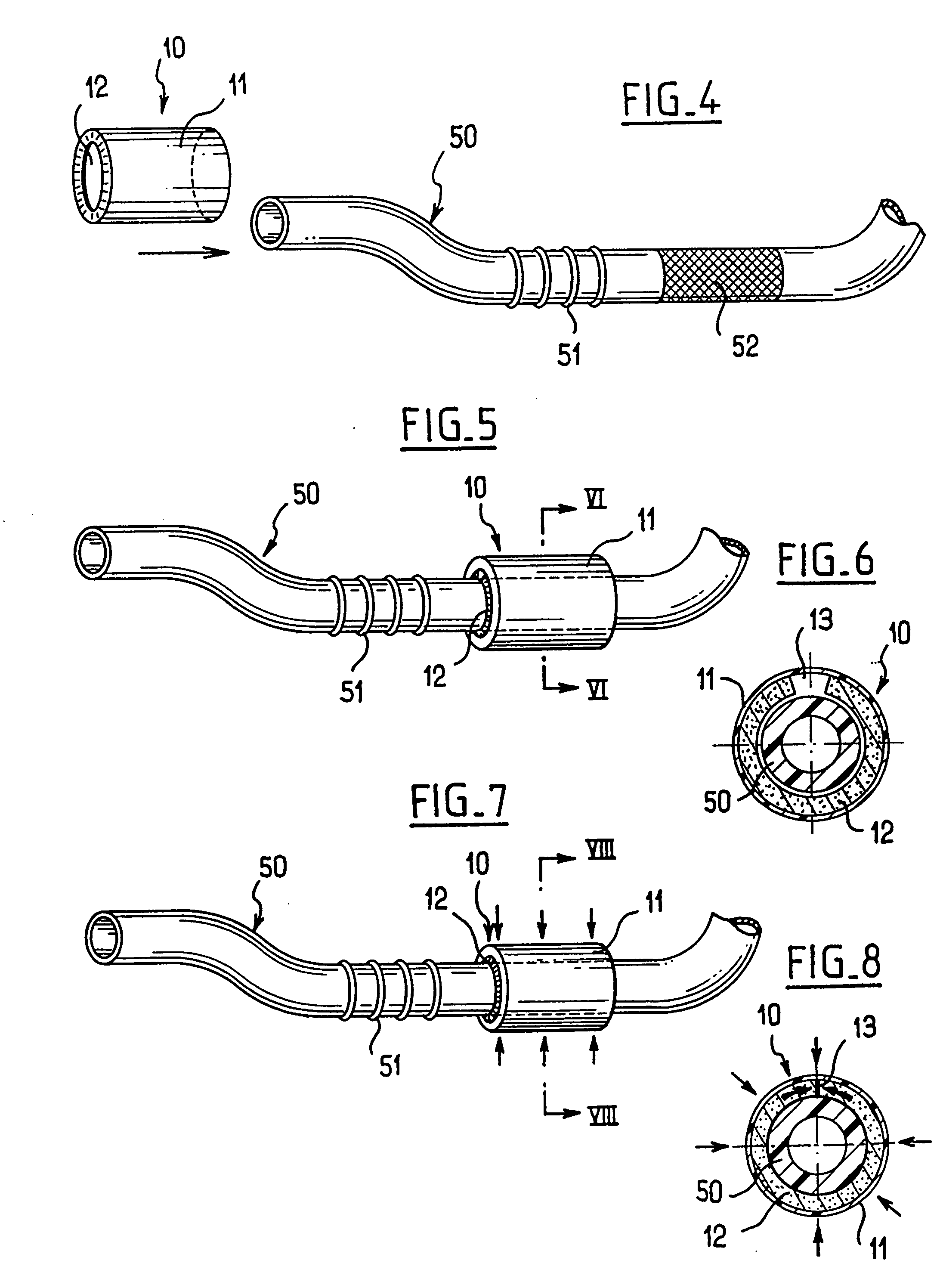
[0031] In FIGS. 1 to 3, there can be seen a spacer referenced 10 for putting into place on a tubular element, which tubular element may be a pipe or a hose of any kind, and of any type of profile, adopting a twisted or straight shape suitable for enabling said tubular element to be used.

[0032] The spacer 10 comprises firstly a sleeve 12 of high compressibility cellular material, said sleeve presenting a wide slot 13 extending along its entire length and defining an essentially cylindrical central passage 15 of diameter that is greater than the nominal diameter of the tubular element concerned. The spacer 10 also comprises a sheath 11 of heat-shrink plastics material surrounding the split sleeve 12 at least as far as its end edges referenced 14

[0033] FIGS. 1 to 3 show the spacer 10 in its state corresponding to the sheath 11 being partially shrunk on the split sleeve 12, which corresponds to the state in which the spacer is stored prior to being put into place and fixed in position ...


PUM


Abstract

A spacer for putting into place on a tubular element includes firstly a sleeve of high-compressibility cellular material, the sleeve presenting a wide slot extending over its entire length and defining a central passage that is essentially cylindrical- and being of diameter greater than the nominal diameter of the tubular element, and secondly a sheath of heat-shrink plastics material surrounding the split sleeve at least as far as the end edges thereof. The sheath is partially shrunk on the split sleeve firstly so as to hold the split sleeve in the open state for putting the spacer into place on the tubular element, and secondly so as to be able subsequently to be heat-shrunk to clamp the split sleeve and fix the spacer in position.

Description

[0001] This application is entitled to the benefit of and incorporates by reference essential subject matter disclosed in French Patent Application No. 02 10442 filed on Aug. 21, 2002. FIELD OF THE INVENTION [0002] The present invention relates to a spacer for putting into place on a tubular element. BACKGROUND OF THE INVENTION [0003] In motor-driven or vibrating structures, it is common practice to use elements that are put into place on tubes or pipes in order to keep said tubes or pipes out of contact with a nearby wall or another tube or another pipe that is nearby. Such elements are conventionally referred to as “spacers”. [0004] In the field of the automotive industry, it is common practice to make use specifically of spacers that are put into place on a flexible or semirigid tubular pipe in order to prevent said tubular pipe coming into contact with an adjacent surface, for example the inside surface of the vehicle hood, or with a surface whose temperature is high, or indeed ...

Claims


Application Information

Patent Timeline
IPC IPC(8): F16L59/02
CPCF16L59/028F16L59/022
Inventor LANCIEN, JEAN-CLAUDE
Owner GREMCO
Why Eureka
Try Eureka