Interchangeable instrument

a technology of interchangeable instruments and instruments, which is applied in the field of medical instruments, can solve the problems of manual exchange of instruments, large time-consuming and laborious, and may be difficult to carry out surgery, and achieve the effect of convenient delivery

Inactive Publication Date: 2005-09-29
AURIS HEALTH INC
View PDF18 Cites 137 Cited by
  • Summary
  • Abstract
  • Description
  • Claims
  • Application Information

AI Technical Summary

Benefits of technology

[0024] In accordance with another aspect of the present invention there is provided a remotely controllable medical apparatus comprising: a remote user interface manually manipulable by a user for sending operation command signals to a signal processor, the signal processor processing the command signals and sending processed signals to a drive mechanism; an instrument exchange mechanism mechanically intercoupled to the drive mechanism; the instrument exchange mechanism comprising a shaft and an instrument delivery mechanism containing two or more selected instruments; the shaft having a lumen which readily receives the selected instruments for insertion and withdrawal from the instrument delivery mechanism; an instrument drive mechanism mechanically intercoupled to the drive mechanism and readily mechanically couplable to and decouplable from an instrument; the instrument drive mechanism being remotely drivable via the user interface to operably couple to and drive an instrument; the instrument being of one of the type of, an articulating instrument and a fluid dispensing instrument.

Problems solved by technology

Thus, a great deal of time may be spent during the surgery simply in exchanging between different types of instruments.
Due to the size and increased complexity of these instruments it may be even more difficult to carry out an exchange due to the need to extract and re-insert through a relatively small incision.
However, even in these more advanced systems there is still a need to manually exchange instruments during a procedure.

Method used


Image

  • Interchangeable instrument
  • Interchangeable instrument
  • Interchangeable instrument

Examples


first embodiment

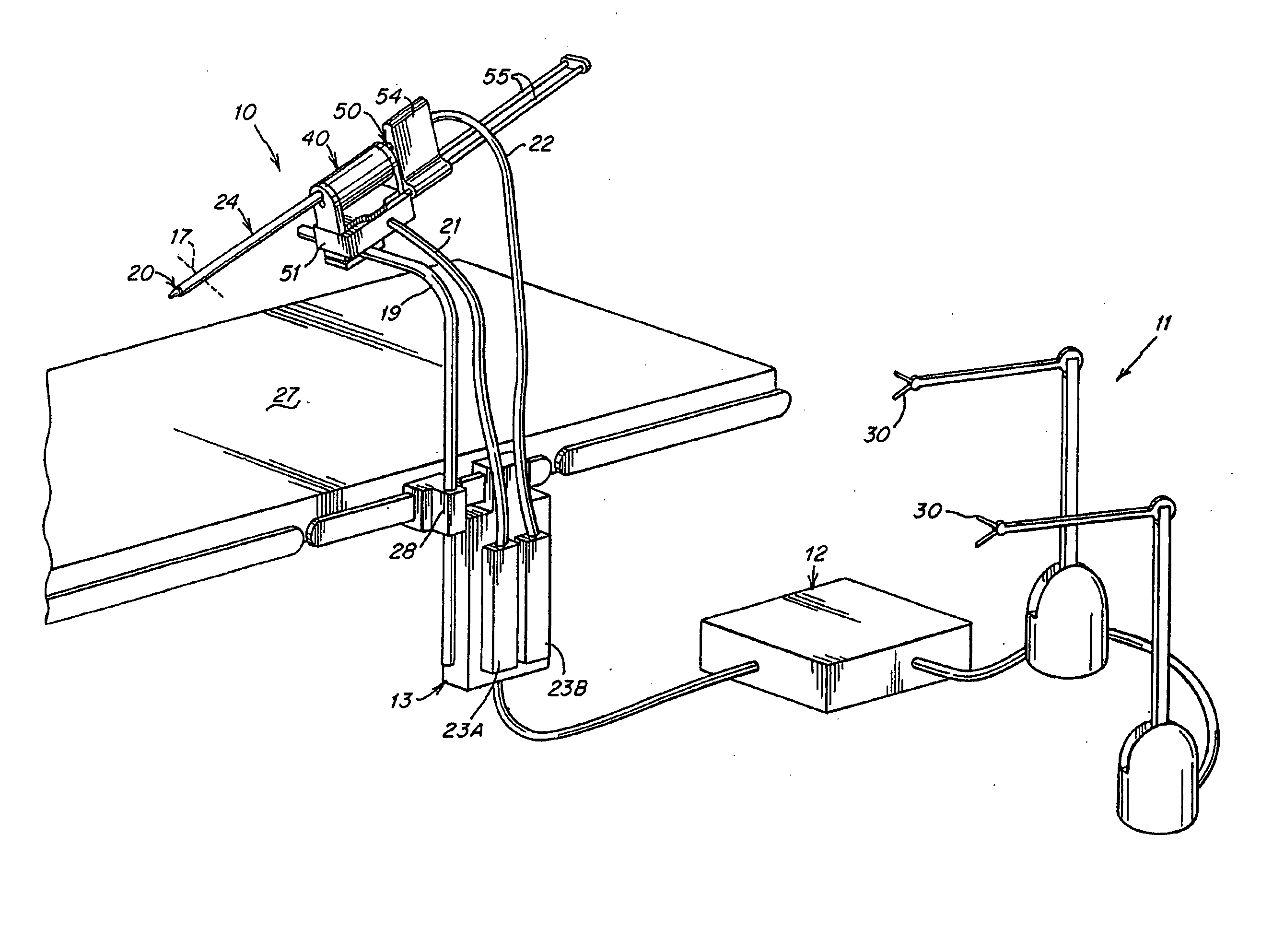
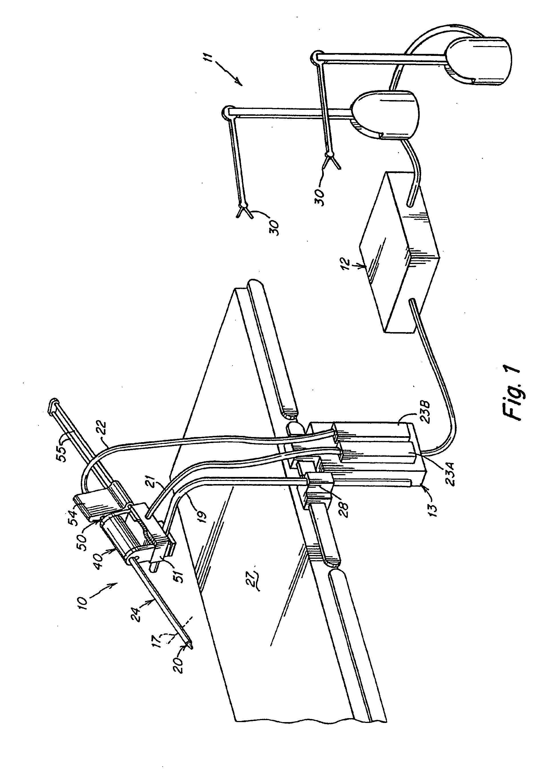
[0050] the invention is illustrated in FIGS. 1-7. FIG. 1 shows a surgical instrument system 10 that performs surgical procedures. The system may be used to perform minimally invasive procedures. The system may also be used to perform open or endoscopic surgical procedures. The system 10 includes a surgeon interface 11, computation system 12, and drive unit 13. The system controls the instrument so as to position either an end effector (tool) or fluid dispensing implement of the instrument 20 at the very distal end of and extending through the outlet guide tube 24. During use, a surgeon may manipulate the handles 30 of the surgeon interface 11, to effect desired motion of the instrument 20 within the patient, at the operative site which is schematically illustrated in FIG. 7. The movement of a handle 30 is interpreted by the computation system 12 to control the movement of the very distal end of the instrument 20.

[0051] The system may also include an endoscope with a camera to remote...

second embodiment

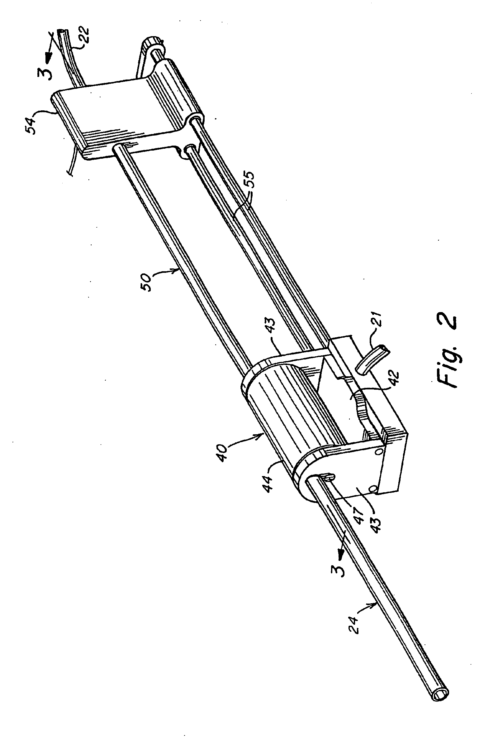
[0053] The surgical system 10 includes two mechanical cable-in-conduit bundles 21 and 22. These cable bundles 21 and 22 terminate at one end at the two connection modules (couplers) 23A and 23B, which removably attach to the drive unit 13. The drive unit 13 is preferably located outside the sterile field, although it may be draped with a sterile barrier so that it may be operated within the sterile field. The other end of the bundles terminate at the surgical system 10. These terminations are shown in further detail in the description of the second embodiment that is described later. Basically cables in the bundle 21 may control; the indexing for controlled rotation of the instrument storage chamber 40; rotation of the guide tube 24; as well as motion of the carriage 54 for control of the linear translation of the driver 50. On the other hand the bundle 22 may control, for example, rotation of the instrument 20 within the guide tube 24, as well as actuation of the tool 18, in the ev...


PUM


Abstract

A system and associated method for delivering to an internal body site a selected one of a plurality of instruments including fluid-dispensing instruments. An instrument storage chamber is providing having passages for separately accommodating the plurality of instruments. An outlet guide tube couples from the instrument storage chamber and receives a selected one of these instruments for delivery to an internal operative site. An indexing mechanism is provided associated with the chamber for causing relative displacement between the instruments and the outlet guide tube. An instrument driver displaces the registered instrument from the chamber into the outlet guide tube for delivery to the internal operative site.

Description

RELATED APPLICATIONS [0001] This is a divisional of U.S. application Ser. No. 10 / 097,923, filed Mar. 15, 2002, which is a continuation-in-part of and claims the benefit of priority from U.S. application Ser. No. 10 / 077,233, filed Feb. 15, 2002; PCT serial no. PCT / US02 / 04495, filed Feb. 15, 2002; PCT serial no. to be assigned (docket no. 08491.7012-00304), filed Feb. 15, 2002; U.S. application Ser. No. 10 / 034,871, filed Dec. 21, 2001; U.S. application Ser. No. 09 / 827,503, filed Apr. 6, 2001, which is a continuation of U.S. application Ser. No. 09 / 746,853, filed Dec. 21, 2000, which is a divisional of U.S. application Ser. No. 09 / 375,666, now U.S. Pat. No. 6,197,017, filed Aug. 17, 1999, which is a continuation of U.S. application Ser. No. 09 / 028,550 filed Feb. 24, 1998, now abandoned. This application is also a continuation-in-part of and claims the benefit of priority from U.S. application Ser. No. 09 / 783,637, filed Feb. 14, 2001, which is a continuation of PCT / USOO / 12553 filed May ...

Claims


Application Information

Patent Timeline
Patent Type & Authority Applications(United States)
IPC IPC(8): A61B17/00A61B19/00A61B19/02
CPCA61B5/0084A61B2017/00477A61B5/015A61B5/04A61B5/415A61B5/416A61B5/418A61B5/4893A61B6/425A61B17/00234A61B17/00491A61B17/29A61B19/026A61B19/22A61B19/2203A61B19/50A61B19/52A61B19/5212A61B19/5244A61B2017/00022A61B2017/00026A61B2017/00039A61B2017/00088A61B2017/00115A61B2017/00362A61B2017/00473A61B2017/00482A61B2019/2211A61B2019/2223A61B2019/223A61B2019/2242A61B2019/2249A61B2019/2292A61B2019/464A61B2019/505A61B2019/5291A61B5/0086A61B90/36A61B34/20A61B2090/064A61B34/70A61B34/71A61B2034/301A61B90/361A61B34/30A61B50/30A61B34/37A61B34/35A61B34/72A61B34/76A61B34/10A61B2034/105A61B2090/365A61B5/24
Inventor BROCK, DAVID L.
Owner AURIS HEALTH INC
Why Eureka
Try Eureka