Buccal tube having flared mesial and distal ends

a technology of mesial and distal ends and buccal tubes, which is applied in the field of orthodontic devices to achieve the effects of reducing office visits, increasing control, and reducing pain

Inactive Publication Date: 2005-11-03
SCHULTZ CHARLES J
View PDF14 Cites 53 Cited by
  • Summary
  • Abstract
  • Description
  • Claims
  • Application Information

AI Technical Summary

Benefits of technology

[0008] This invention is designed to satisfy the need for increased control while allowing greater patient comfort and fewer office visits.

Problems solved by technology

The center portion of each tube is of sufficient axial length to retain the arch wire in the buccal tube without loss of control, a problem with the prior art.

Method used


Image

  • Buccal tube having flared mesial and distal ends
  • Buccal tube having flared mesial and distal ends
  • Buccal tube having flared mesial and distal ends

Examples


Embodiment Construction

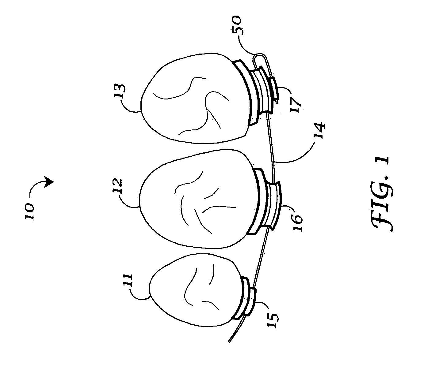
[0017] Referring to the drawings, FIG. 1 is a schematic of a portion of a patient's dentition (10) that is being orthodontically treated for malocclusion, including a bicuspid (11), a mesial first molar (12) and a distal second molar (13). An arch wire (14) is secured to the bicuspid by a conventional bracket (15) and to the molars by means of buccal tubes (16 and 17) of the invention.

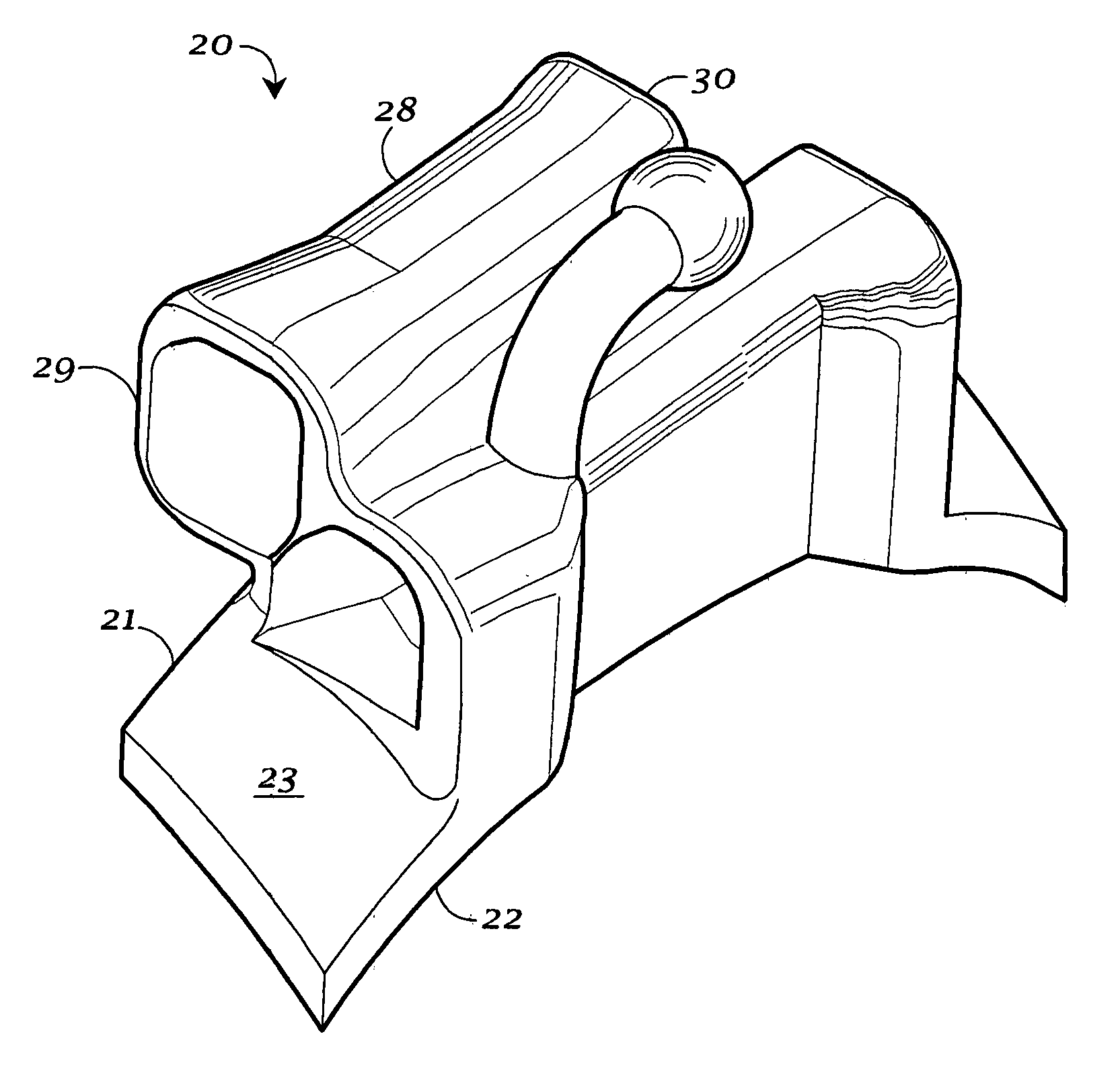
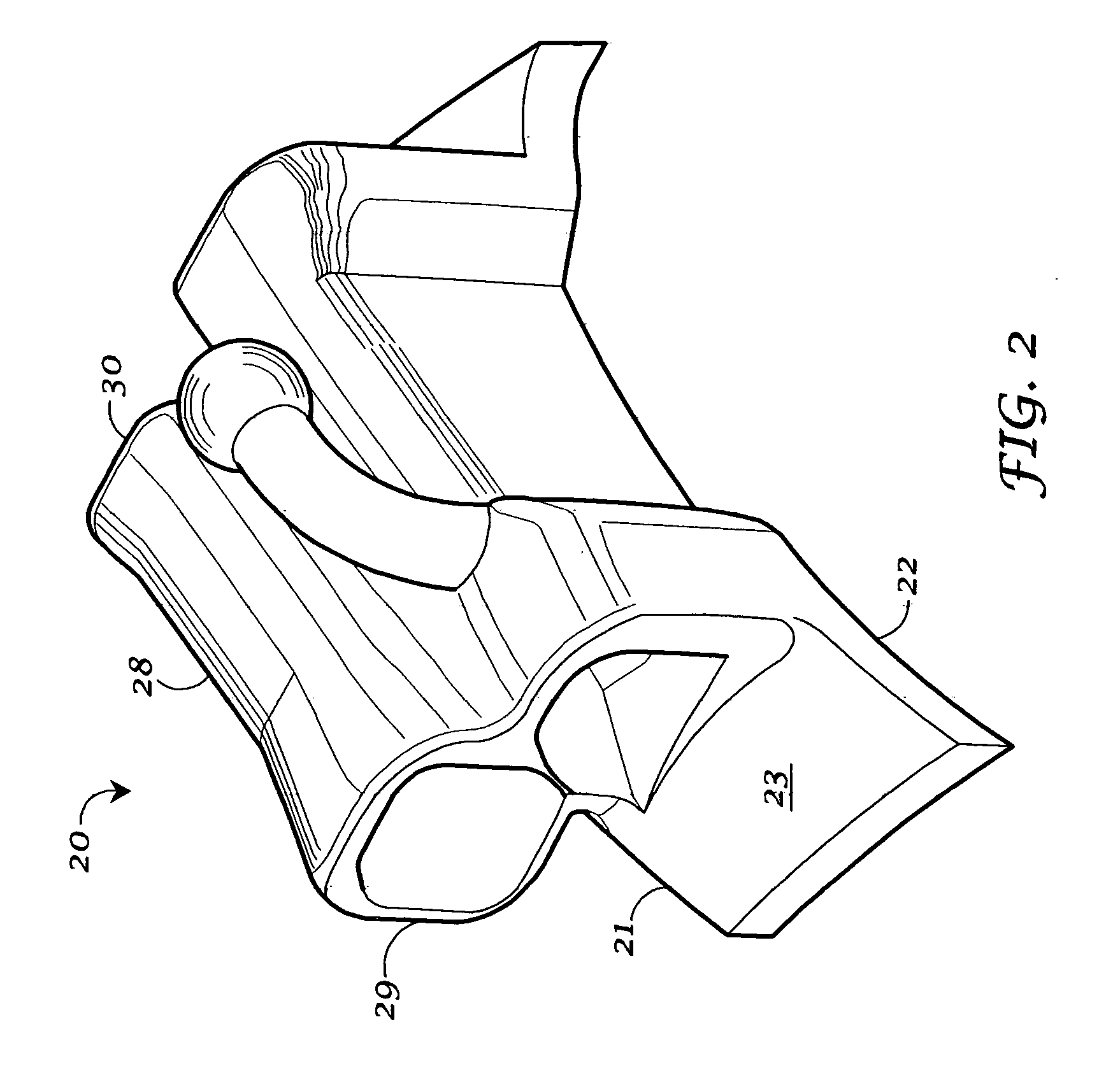
[0018] Referring to FIGS. 2-4, a buccal tube device of the invention similar to the buccal tube (17) attached to the distal molar (13) in FIG. 1 is shown in detail. FIG. 2 is an isometric projection of the twin tube orthodontic device (20).

[0019] The orthodontic device (20) of the invention, preferably includes a flange (21) having a base surface (22) for attachment to a tooth surface and an upper surface (23) for supporting the body or structure (24) for securing an arch wire, (not shown but similar to the arch wire (14) of FIG. 1). The device structure, as shown in the preferred embodiment of FIG. ...


PUM


Abstract

The invention is a buccal tube for securing an orthodontic wire to a tooth. The device includes a base or flange for attaching to a tooth and one or more tubes fixed to the base, each tube having a bore for receiving an arch wire. The tube bore includes mesial and distal ends and a center portion. The center bore portion has a shape and dimensions for receiving and securing the wire. Both the mesial and distal bore ends of the tube are flared to accommodate receiving the arch wire, particularly when extending an arch wire from a first mesial buccal tube to a second distal buccal tube as adjacent molars are engaged in the orthodontic process.

Description

FIELD OF INVENTION [0001] This invention is directed to orthodontic devices, such as buccal and lingual tubes, for securing an orthodontic wire to a tooth. More particularly, the invention focuses upon buccal tube improvements that allow, as an orthodontic treatment progresses, easier extension and securing of an arch wire between two adjacent molars. BACKGROUND OF THE INVENTION [0002] As orthodontic treatment progresses it is often necessary to extend an arch wire and secure it to an adjacent, usually most distal molar. In some cases it is required to apply aligning forces to a newly erupted second molar. In others, it is necessary to cinch up a wire as alignment and leveling improves and slack in a wire is created between visits. [0003] To accommodate second molars, orthodontists have long utilized a buccal tube attached to a first molar having a convertible or removable cover. When it is time to extend an arch wire to a distal molar, a second buccal tube is attached to the second...

Claims


Application Information

Patent Timeline
Patent Type & Authority Applications(United States)
IPC IPC(8): A61C3/00A61C7/28
CPCA61C7/282
Inventor SCHULTZ, CHARLES J.
Owner SCHULTZ CHARLES J
Why Eureka
Try Eureka