System, Method And Apparatus For Tooth Implant Planning And Tooth Implant Kits

a technology for tooth implants and kits, applied in the field of restoration dentistry, can solve the problems of reducing the service life of the implant, affecting the quality of the implant, and the inability to accurately plan the jaw for the fixtures supporting the prosthesis, so as to facilitate the proper placement of the fixture, maximize the bone surface area of the implant, and improve the service life.

Inactive Publication Date: 2010-04-29
INPRONTO
View PDF43 Cites 262 Cited by
  • Summary
  • Abstract
  • Description
  • Claims
  • Application Information

AI Technical Summary

Benefits of technology

[0059]A systematic approach to implant planning and selection in accordance with the foregoing principles of invention may include computer simulation software based on CAT scan data that allows virtual implant surgical placement based on a barium impregnated prototype of the final prosthesis. This predicts vital anatomy, bone quality, implant characteristics, the need for bone or soft tissue grafting, and maximizing the implant bone surface area for the treatment case creating a high level of predictability. Computer CAD / CAM milled, selective laser sintering, stereo lithography, or other rapid prototyping method based drill guides can be developed for the surgeon to facilitate proper fixture placement based on the final prosthesis occlusion and aesthetics. Treatment planning software can also be used to demonstrate “try-ins” to the patient and practitioners on a computer screen. Digital data from a CAT scan (such as an iCAT or a NewTom) can provide accurate simulations that are easily understood by patients and practitioners. When options have been fully discussed between patient and surgeon / restorative dentist, software adapted to practice the methods of the invention can be used to produce precision drill guides and other restorative components.
[0060]In accordance with the foregoing objectives, it will be appreciated that aspects of the invention offer benefits to doctors and related health professionals, as well as to the patient. The invention can eliminate the need for significant capital investments, reduce administrative time and coordination, reduce trial and temporary dentures, and reduce the probability of poor outcomes, yielding more profit and less hassle. As for patients, in comparison to existing implant practices, there is less elapsed time, fewer office visits, longer implant durability, better esthetics, less pain, significantly reduced post operative complications, and an appreciable reduction in the overall costs associated with an implant.

Problems solved by technology

Unaided manual preparation of a jaw for fixtures supporting prosthesis is challenging, because of the difficulty in estimating positions and angles accurately by the naked eye, within a deep hole of small diameter in a patient's mouth with limitations to opening.
Even if the work is being done by an experienced dentist or oral surgeon, chances for location, angular or orientation errors are great.
a) The human jawbone is highly variable in thickness and density from location to location, and varies from person to person. Thus, for a given individual's jaw, certain implant locations are preferable to others because of bone strength variations.
b) For implant attachment strength, the optimal direction at which the fixture should pass into the bone varies from one jaw location to another, and bone configurations are different from person to person. If the hole in the bone is drilled at an incorrect location and / or angle, the tip of the fixture may pass through the bone and out the far side, weakening its attachment strength and in some instances compromising the integrity of the entire fixture. Protruding fixture tips also raise patient objections on cosmetic grounds.
c) Poor placement of fixtures can be a source of problems in installing and using a prosthesis. If fixtures exit the jaw unparallel with one another it may be more difficult to align the prosthesis to the fixtures properly. In addition, when fixture axes are far from parallel, biting forces will translate from purely compressive force to bending force more likely to fracture the bone, the fixture itself or the prosthetic screws holding the prosthesis to the fixtures.
Safety and aesthetics are usually considered during this process (as noted above), but due to a lack of an available systematic analysis of the overall restorative device functions after implantation, the fixture may not function as intended.
This may lead to subsequent return trips to the restorative dentist or surgeon, replacement of crowns or repair of the supporting jaw due to extensive bone loss, infections, etc.
Implant loads from chewing and parafunction can exceed the physio biomechanic tolerance of the implant bone interface and / or the titanium material itself, causing failure.
This can be a failure of the implant itself (fracture) or bone loss, or a “melting” or resorption of the surrounding bone.

Method used


Image

  • System, Method And Apparatus For Tooth Implant Planning And Tooth Implant Kits
  • System, Method And Apparatus For Tooth Implant Planning And Tooth Implant Kits
  • System, Method And Apparatus For Tooth Implant Planning And Tooth Implant Kits

Examples


examples

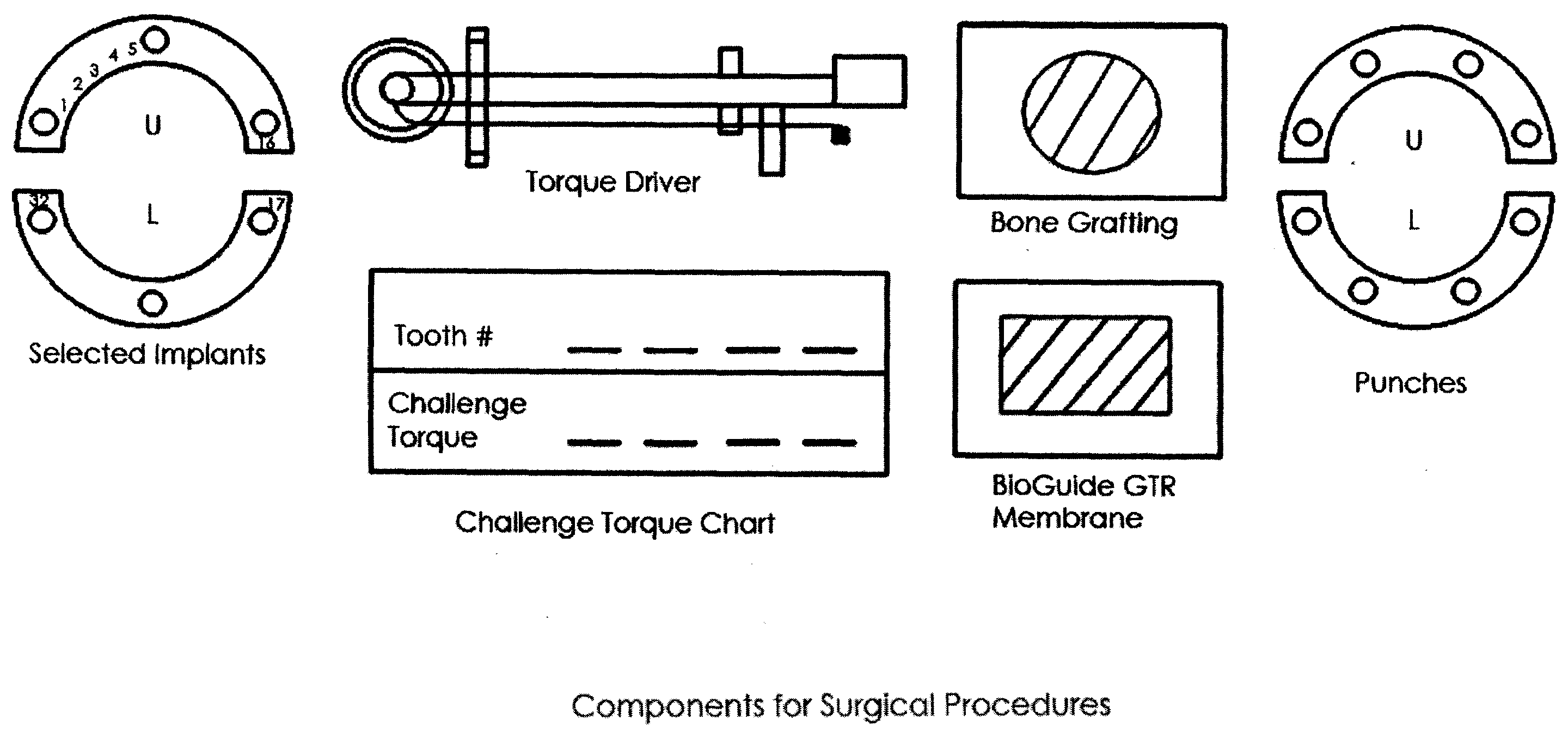
[0174]The following provide examples of methods of design and ultimate manufacture of a healing, temporary and final abutment, temporary and final crowns and bridges, and a surgical guide.

[0175]The healing, temporary and final abutment may have a unique design and manufacturing process. For a healing abutment:

[0176]1. Define the core of the abutment height and width “#5”—The core should be between 1-7 mm in Height.

[0177]2. Insert the axis hole chimney

[0178]3. Export a STL file for 3-D printing

[0179]For a temporary abutment

[0180]1. Define the core of the abutment height and width “#5”—The core should be between 1-7 mm in Height. Then define the body of the abutment shape, height and angulation.

[0181]2. Insert the axis hole chimney

[0182]3. Export a STL file for 3-D printing

[0183]For a final abutment:

[0184]1. Define the core of the abutment height and width “#5”—The core should be between 1-7 mm in Height. Then define the body of the abutment shape, height and angulation.

[0185]2. Inser...


PUM

PropertyMeasurementUnit
heightaaaaaaaaaa
heightaaaaaaaaaa
Heightaaaaaaaaaa

Abstract

Systems and methods support dental implant patient scheduling and treatment process relating to packaging one or more dental appliances as a kit which is readily used by dental professional during surgery, by communicating manufacturing progress information with a doctor over a network and performing patient scheduling and treatment when the dental appliances reach a certain manufacturing progress. A network-based service may also provide a doctor with a treatment solution including a surgical kit derived from patient data.

Description

[0001]This application claims priority as a Continuation-in-Part of U.S. application Ser. No. 12 / 260,323 entitled “System, Method and Apparatus for Tooth Implants”, and filed on Oct. 29, 2008, the disclosure of which is hereby incorporated by reference in its entirety for all purposes.BACKGROUND OF THE INVENTION [0002]1. Field of the Invention[0003]The present invention relates to restorative dentistry; specifically, dental implants relating to surgical, restorative and prosthetic dentistry.[0004]2. Background of the Invention[0005]Implants are now a standard way to attach a dental prostheses. One fixture may support a single tooth replacement, usually cemented or screwed atop an abutment. An implant supported bridge (also called a bar or frame) is used when several teeth are missing.[0006]FIGS. 1A and 1B show the basic anatomical structure for a tooth, and a comparison between this structure and the structure most commonly used for a non-removable dental implant. Referring to FIG. ...

Claims


Application Information

Patent Timeline
Patent Type & Authority Applications(United States)
IPC IPC(8): A61C8/00B65D83/00
CPCA61C1/084A61C13/0019A61C13/0004
Inventor KARKAR, ISSA GEORGEWEN, HUAFENGKARKAR, PAUL GEORGE
Owner INPRONTO
Why Eureka
Try Eureka