
Computer-enabled, networked, facility emergency notification, management and alarm system

a technology of emergency notification and computer, applied in the field of computer enabled, networked, facility emergency notification, management and alarm system, can solve the problems of little, if any, flexibility in the alarm and response system, communication failure, and alarm giving no assistance to responding personnel, so as to prevent loss of control functionality, increase the level of directed action, and facilitate the effect of dissemination

Active Publication Date: 2006-05-25
SIEMENS SWITZERLAND
View PDF31 Cites 441 Cited by
  • Summary
  • Abstract
  • Description
  • Claims
  • Application Information

AI Technical Summary

Benefits of technology

[0008] The inventive system comprises a secure, redundant, verifiable, computer-enabled, networked, facility emergency notification, rapid alert management and alarm systems installed in public, private, and government buildings, and outdoor areas for which there is a need for rapid alerts to occupants or attendees of the occurrence of impending or in-progress dangerous or threatening events. More particularly, the invention relates to highly secure, access-controllable, flexible, hierarchical, local, regional, national or international fast alert systems comprising computer-enabled and network linked apparatus, software, and methods enabling rapid dissemination from a central station, or decentralized or mobile location, of alerts of the occurrence of threatening or dangerous events in a series of hierarchical, increasing levels of directed action to be taken by the occupants. In addition, the inventive system can cause initiation of appropriate responsive actions by occupants based on type and level of alert, monitoring and controlling activity of occupants and event responders (e.g., security, fire and medical personnel) during the course of the event or danger, while archiving times and natures of events, responses and other data, including audio or / and video recordings, about the various occurrences, events, alarms, and responses, until the situation returns to normal and an all clear signal is given. Links to, or self-contained, databases can be accessed to provide building and site plans to assist initiating and propagating alerts, change in alert status, and in the response planning and execution. The system has redundancy capability built-in to prevent loss of control functionality in the event of component failure.
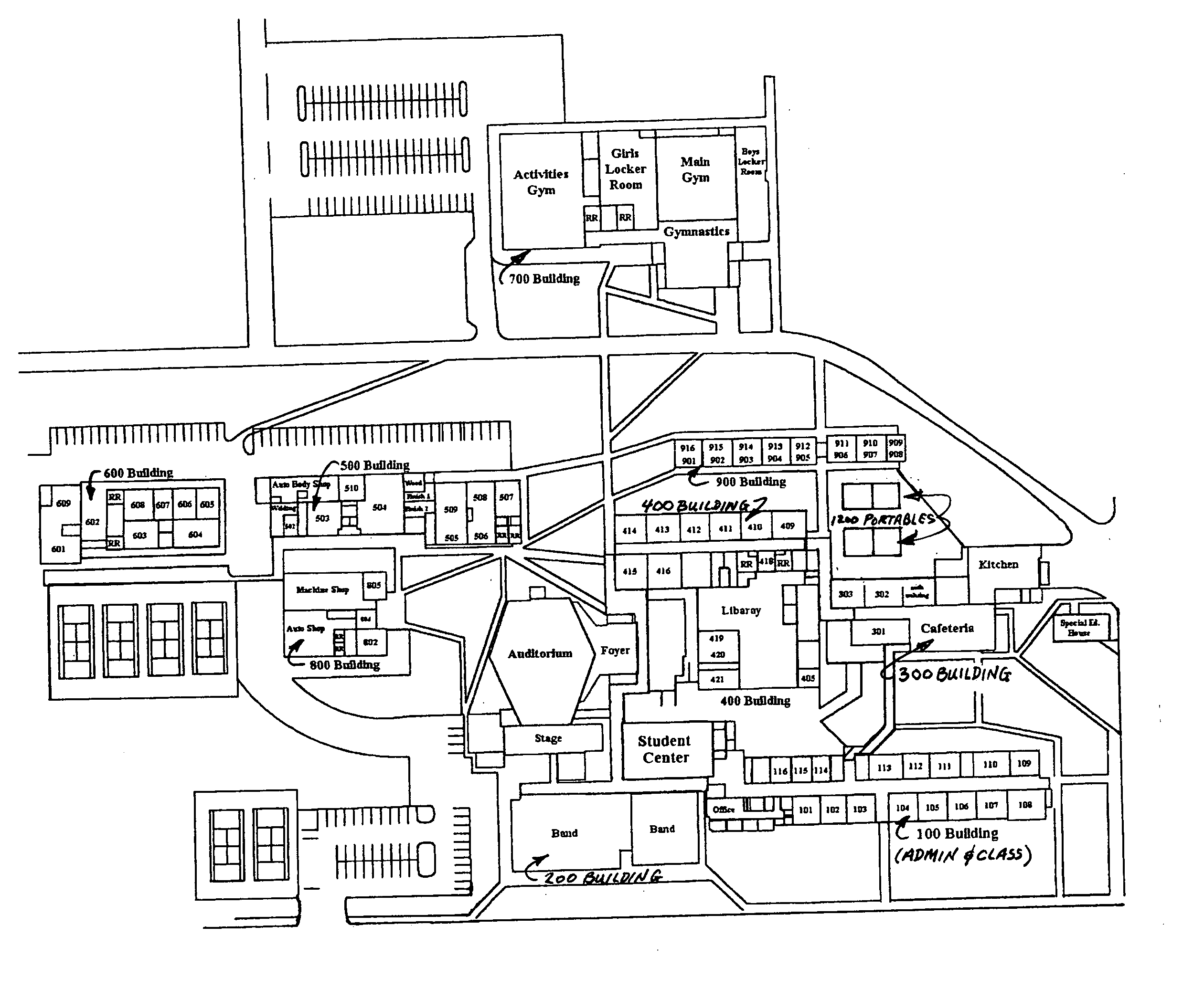
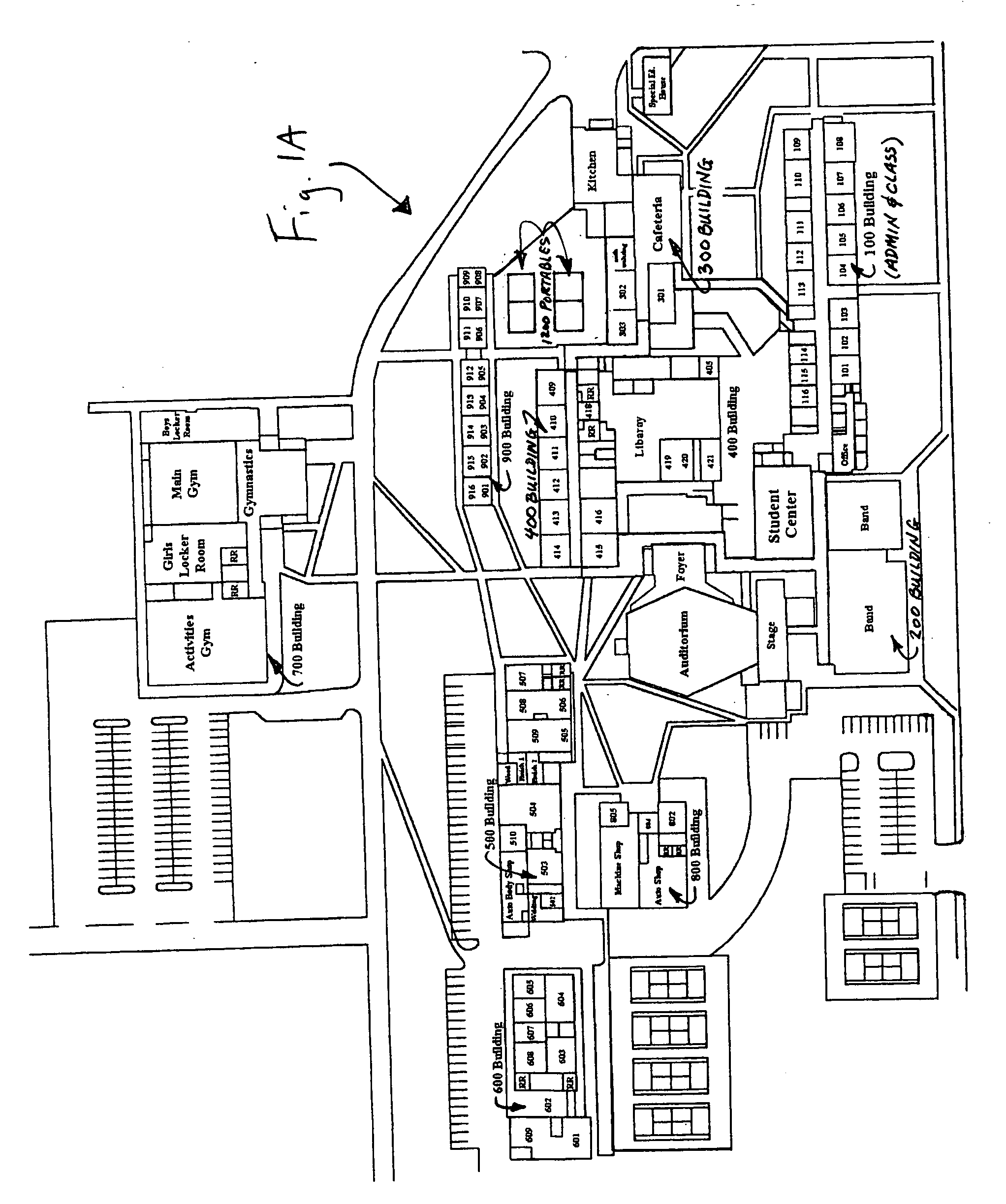
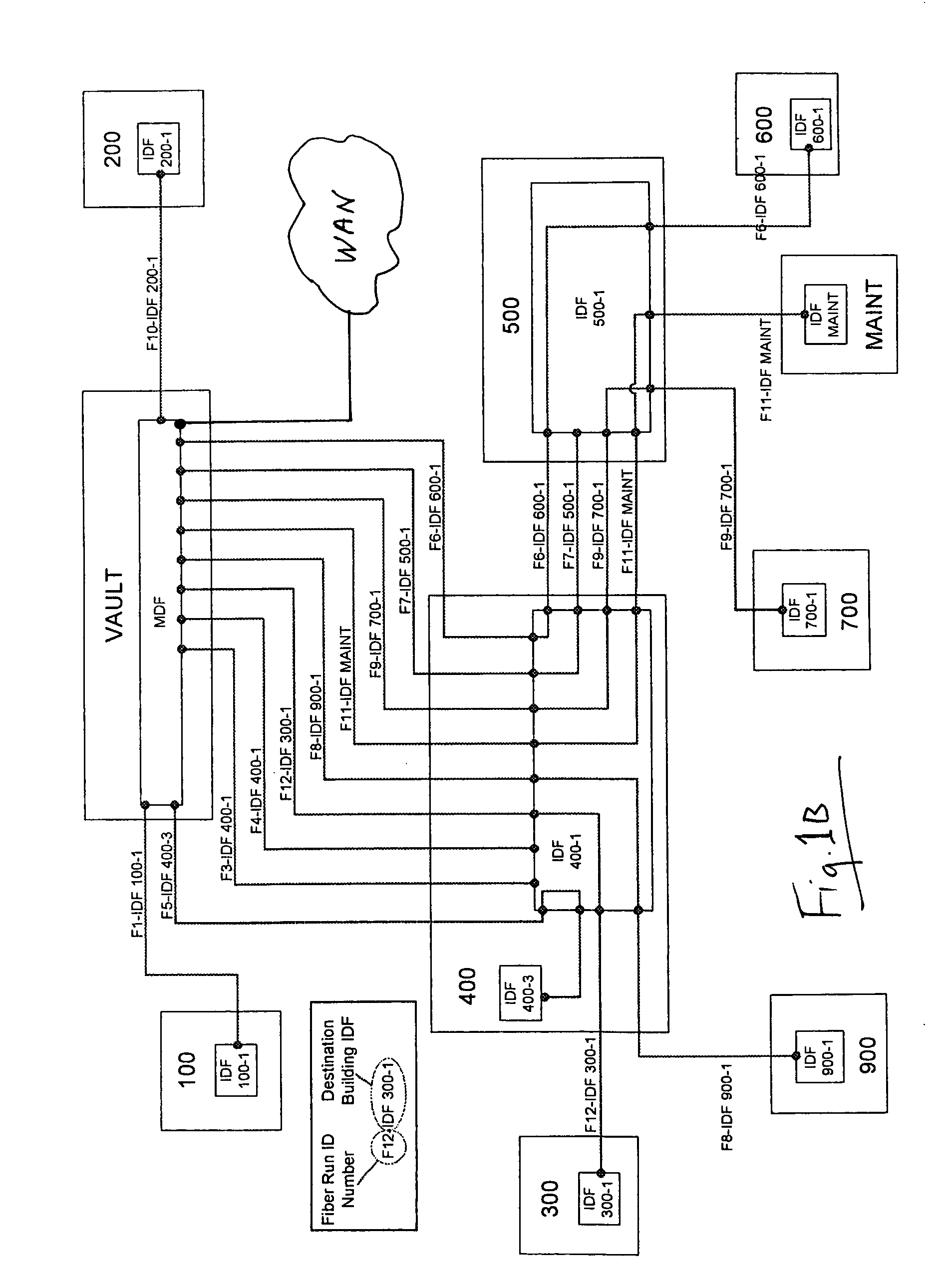
[0011] Embodiments of the inventive rapid alerting system are both site and event specific, e.g., the inventive system is flexible enough to be specific to the designed alerting domain (whether a single building, a group of buildings such as a campus, in an outdoor area, or a combination of these), to pre-defined types of dangers and events, and to combinations of them. Thus, the system can be configured to be tailored to the particular complex of building(s) and their surroundings to provide the necessary capability to rapidly alert occupants therein, including providing occupants with suitable information so that they can respond efficiently and effectively to anticipated dangers, hazardous occurrences and rapidly evolving events. Embodiments of the inventive system range from a simple, small network in a single building, to a complex, hierarchical network in a multiple building campus over a large geographic area.
[0028] Accordingly, the inventive system comprises an application specific Internet Protocol-based, networked alert system for public or private facilities that is accessible from a plurality of sites to provide a high degree of flexibility in selection, installation and triggering of alert devices, to provide to emergency responders a source of easily accessed data and information about the alarmed facility, the nature and time of the alert, allows for immediate changes from one type or status of alert to another including an alert that notifies occupants of when the danger has passed, provides means for electronic written and / or audio communication between networked computers as to the nature of the emergency event, to establish a means of remote physical, real-time viewing of, or / and listening-in on, dangerous or hazardous events in progress, and to enable linking of local systems to regional or national security networks for real time receipt and monitoring of information on hazardous events or situations beyond the local boundary, and to alert regional or national authorities of hazardous or dangerous local events, and permit monitoring of events in real time as they unfold.

Problems solved by technology

There are many examples of communications failures incident to emergency situations in facilities with this type of alarm installation.
Typically, the alarms give no assistance to responding personnel and do not permit clarifying or change in status of event-in-progress information being provided to the occupants to supplement the initial raw alarm information.
There is little, if any, flexibility in the alarm and response system; communication is tenuous, slow, and difficult to control and subject to failure.
Installation of a centrally controlled alarm bells or horns does not enable alerting only selected sub-areas of the sites to dangerous or hazardous events or situations without alarming and evacuating the entire complex.
This leaves the evacuated population to learn by rumor the nature of the event (which is usually incomplete or wrong), provides no assistance in monitoring the progress of events or directing rescue action to rapid response personnel (e.g., police, fire, medical, SWAT, or hostage teams).

Method used


Image

  • Computer-enabled, networked, facility emergency notification, management and alarm system
  • Computer-enabled, networked, facility emergency notification, management and alarm system
  • Computer-enabled, networked, facility emergency notification, management and alarm system

Examples


first embodiment

[0051]FIG. 2A shows alarms for the inventive system 10 in which a central control computer 12 is linked via network cable 14 to a powered network switch 16. The network controlled alarm units 18a, 18b, 18c and 18d are installed in parallel, connected to the network switch 16 using network cable. The control computer is configured with an operating system standard (such as Windows XP Pro, Linux, or MAC OS10) and alarm system application software that functions per the logic of FIG. 4 and as further described herein. It also includes graphic displays of the type shown in the screen views illustrated in FIGS. 5 through 8. In the preferred embodiment of FIG. 9, the rapid alert initiation, management and archiving application program is resident in an application server (also known as a web server) linked in the network, and the computers 12 of FIGS. 2A, 2B, 3 and 10-12 are client computers from which access to the rapid alert program is launched via browser. The inventive system is comp...

second embodiment

[0053] In an important alternate, second embodiment, the powered network switch 16 can be replaced with a combination of a regular network switch 16′ and individual power injectors 22a-22d associated with each alarm branch. When signaled by the computer 12 the un-powered network switch 16 triggers the computer-selected power injectors 22a, 22b, 22c, and 22d to turn on power to their associated alarm unit 18a, 18b, 18c, or 18d.

third embodiment

[0054]FIG. 2B shows alarms in a parallel-series configuration that is similar to the configuration of FIG. 2A, except that each alarm branch 24a through 24c has a series of alarms 18a through 18d rather than a single alarm. Operation of the system permits activation of one or more of the parallel branches, but requires that all of the alarms in that particular branch, 24a, or 24b, or 24c, operate together.


PUM


Abstract

Secure, verifiable, computer-enabled, LAN / WAN / Wireless networked, facility emergency notification, rapid alert management, and occupant alarm systems for public, private, and government buildings, and outdoor areas for which there is a need for rapid alerts to occupants or attendees of the occurrence of impending or in-progress dangerous or threatening events. The inventive system is a highly flexible rapid alert initiation, management and archival system comprising computer-enabled and network-linked apparatus, software, and methods enabling rapid dissemination from a central station or decentralized location of alerts of the occurrence of threatening or dangerous events in a series of hierarchical, increasing levels of directed action to be taken by the occupants, and permits monitoring and controlling activity of occupants during the event, archiving event data, including audio or / and video recordings until the situation returns to normal and an all clear signal is given. Databases provide site plans to assist in the response planning and execution.

Description

CROSS REFERENCE TO RELATED APPLICATIONS [0001] This application is related to U.S. Provisional Application Ser. No. 60 / 610,810 filed by the same inventors on Sep. 17, 2004 under the title: Fast Alert System, A Computer Enabled, Networked Facility Emergency Notification Management and Alarm System, and to U.S. Provisional Application Ser. No. 60 / 656,198, filed by the same inventors on Feb. 24, 2005 under the title: Fast Alert System II—A Computer Enabled, Networked Facility Emergency Notification, Management and Alarm System, the disclosures of which are hereby incorporated by reference and the benefit of the filing dates thereof are claimed under 35 USC §§ 119, 120, ff.FIELD [0002] This invention relates to secure, redundant, verifiable, computer-enabled, networked, facility emergency notification, rapid alert management and alarm systems installed in public, private, and government buildings, and outdoor areas for which there is a need for rapid alerts to occupants or attendees of ...

Claims


Application Information

Patent Timeline
Patent Type & Authority Applications(United States)
IPC IPC(8): G08B13/00
CPCG08B7/06G08B25/016G08B25/001G08B25/14G08B27/005G08B25/085
Inventor REYES, TOMMY DEANTHOMPSON, GARRY OREN
Owner SIEMENS SWITZERLAND
Learn More