Apparatus for connecting a bone fastener to a longitudinal rod

a technology of bone fasteners and apparatuses, which is applied in the field of spinal fixation systems, can solve the problems of inability to achieve 100 percent alignment of the vertebral column relative to the longitudinal rod, the fixed distance between the head of the pedicle screw and the screw head remains problematic, and achieves the effect of preventing relative rotation

Inactive Publication Date: 2005-11-10
DEPUY SYNTHES PROD INC
View PDF58 Cites 204 Cited by
  • Summary
  • Abstract
  • Description
  • Claims
  • Application Information

AI Technical Summary

Benefits of technology

[0013] The rod coupler bore engaging portion may comprise a bottom end having an increased portion having a dimension greater than that of the second bore, preventing the rod coupler from passing all the way through the coupling when the coupler is inserted into the bore. This increased portion may comprise a conical flange, and the second bore may have a corresponding conical recess adjacent the bottom surface of the coupling. The conical flange and recess may have corresponding engagement surfaces, and at least one of the engagement surfaces may have serrations to prevent relative movement of the flange and coupling bore.
[0028] The connector articulating portion may comprise an increased portion having a dimension greater than that of the second bore, such that when the rod coupler is inserted into the second bore, the increased portion prevents the rod coupler from passing through the coupling. The increased portion may comprise a conical flange, and the second bore may have a corresponding conical recess adjacent to the coupling portion bottom surface. The conical flange and bore may have corresponding engagement surfaces, and at least one engagement surface comprises serrations to prevent relative rotation between the flange and bore.

Problems solved by technology

Despite the development of new connecting techniques, such as the use of jaws with polyaxial bearings to connect the screws and the longitudinal rod, the intra-operative connection of the two elements remains problematic, particularly in cases of heavy spinal deformities.
The problem lies in the fixed distance between the head of the pedicle screw and the longitudinal carrier.
A variable distance between the screw head or the end portion of the hook and the longitudinal rod carrier is desirable, because achieving 100 percent alignment of the vertebral column relative to the longitudinal rod is not always possible.

Method used


Image

  • Apparatus for connecting a bone fastener to a longitudinal rod
  • Apparatus for connecting a bone fastener to a longitudinal rod
  • Apparatus for connecting a bone fastener to a longitudinal rod

Examples


Embodiment Construction

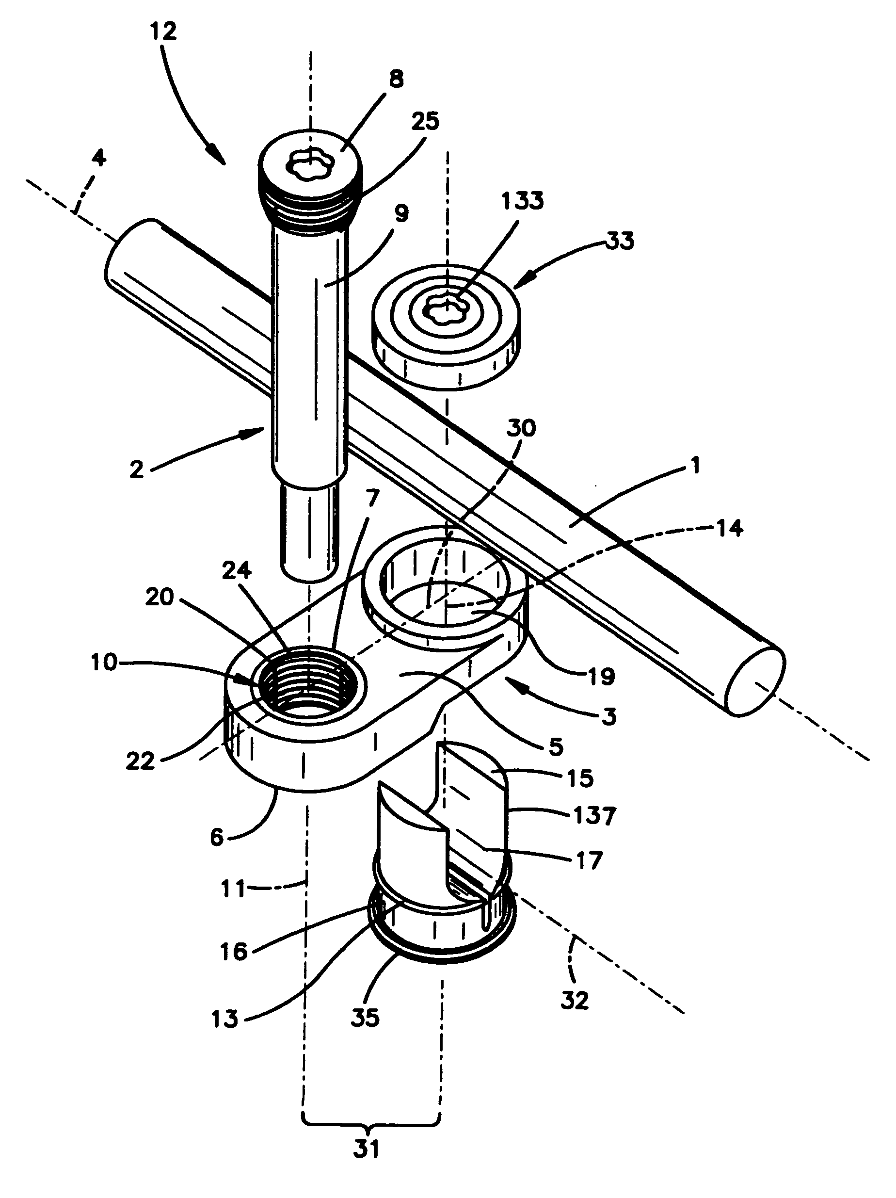
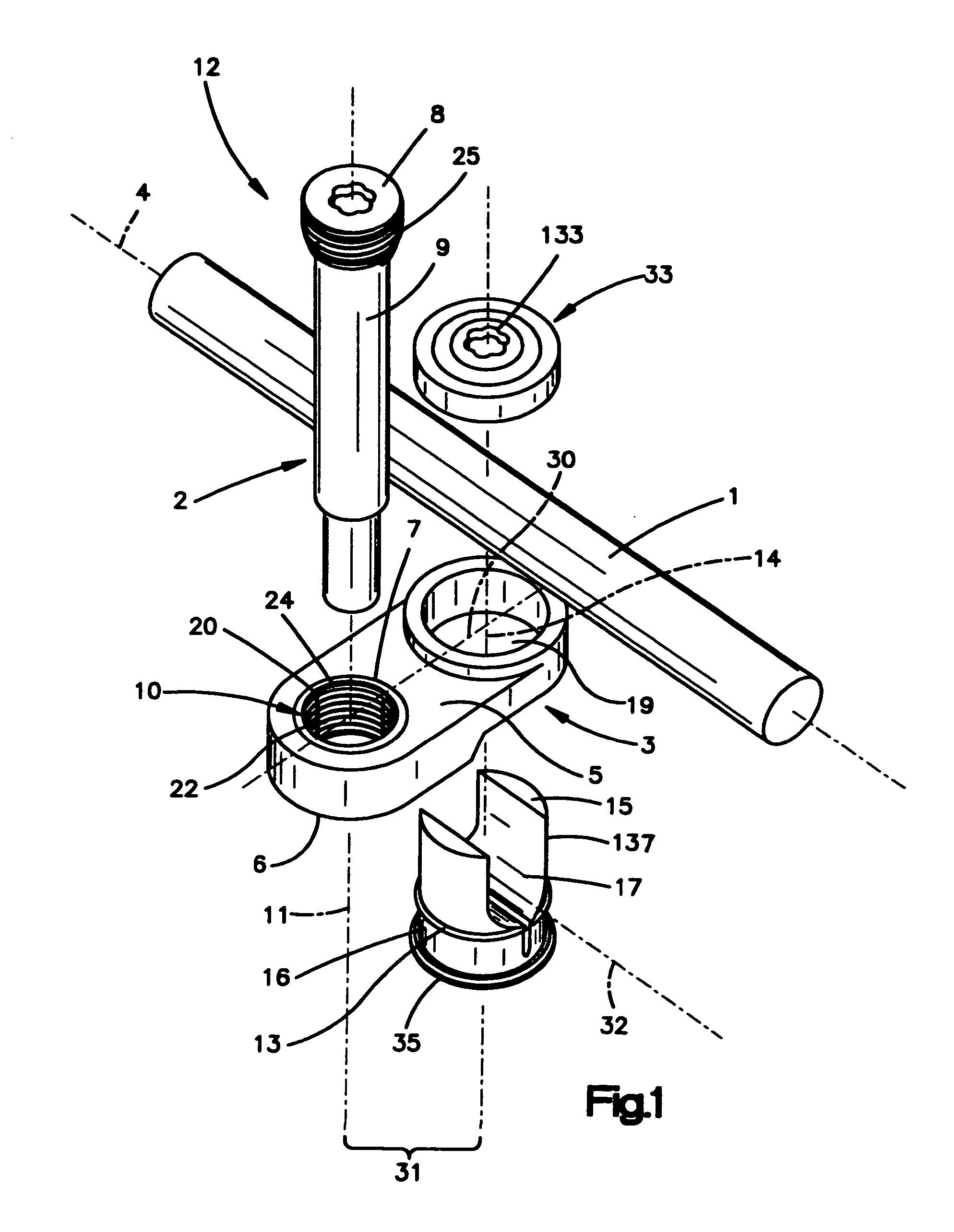
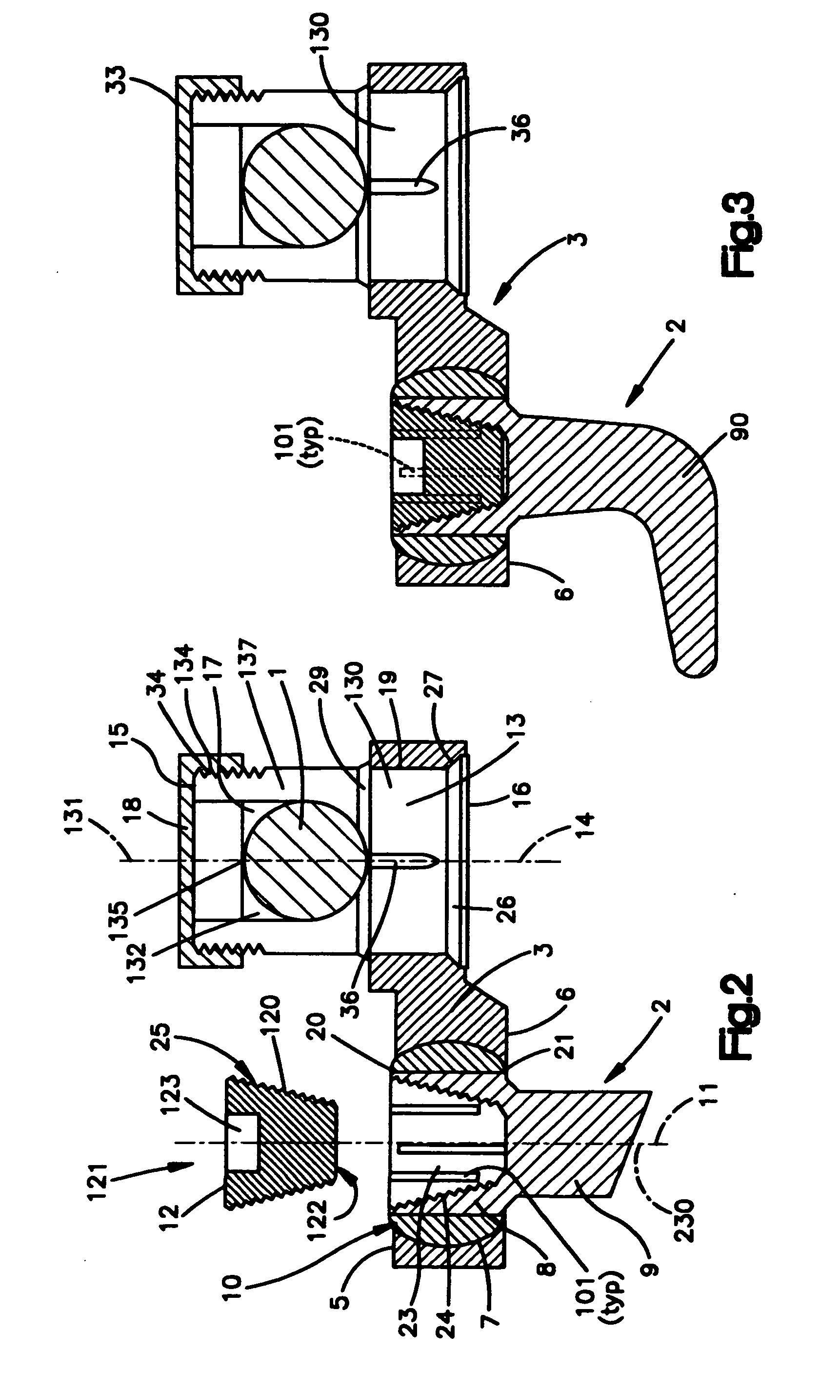
[0035]FIGS. 1 and 2 show a coupling 3, a fastener holding member 10, a tensioner 12 for releasably fixing a bone fastener 2, a rod coupler 13, and a rod locking element 33 configured for releasably fixing a longitudinal rod 1 to coupling 3. Coupling 3 has a longitudinal axis 30, a top surface 5 configured to contact longitudinal rod 1, a bottom surface 6, and a fastener coupling bore 7 which connects top and bottom surfaces 5, 6. Fastener coupling bore 7 further has an axis 11 that is substantially perpendicular to the coupling longitudinal axis 30. In addition, coupling 3 has a rod coupling bore 19 which connects top and bottom surfaces 5, 6 and has an axis 14 which is substantially parallel to fastener coupling bore axis 11. The fastener and rod coupling bores 7, 19 are separated by a distance 31 measured along the coupling longitudinal axis 30.

[0036] The rod coupling bore 19 is configured to slidingly receive a cylindrical articulating portion 130 of longitudinal rod coupler 13 ...


PUM


Abstract

A device for connecting a bone fastener to a longitudinal rod has two bores spaced a distance apart and generally parallel axes. A holding member may be associated with one bore, the holding member configured to engage a bone fastener such as a bone screw or pedicle hook. A rod coupling member may be associated with the other bore, the coupling member configured to engage a longitudinal rod. The holding member and rod coupling member both are configured to articulate within their respective bores, thus allowing the rod and rod coupling, as well as the holding member and bone fastener, to rotate about both bore axes. The holding member and rod coupling member also separately lockable to allow independent locking of the bone fastener and the rod to the connector, thus preventing or enabling relative rotation as desired.

Description

CROSS-REFERENCE TO RELATED APPLICATIONS [0001] This is a continuation of co-pending U.S. application Ser. No. 10 / 372,345, filed Feb. 24, 2003, now U.S. Pat. No. ______, which is a continuation of International Patent Application No. PCT / CH00 / 00449, filed Aug. 24, 2000, the entire contents of both are expressly incorporated herein by reference thereto.FIELD OF THE INVENTION [0002] The invention relates to spinal fixation systems and, in particular, to a device for adjustably connecting a bone fastener to a longitudinal rod. BACKGROUND OF THE INVENTION [0003] In posterior treatment of spinal deformities, pedicle screws or hooks are used to connect vertebral bodies to a longitudinal rod. Prior to implantation, the longitudinal rod is shaped in a particular form so as to correct the deformity of the vertebral column. This technique has proved successful and has been considered state of the art. [0004] Despite the development of new connecting techniques, such as the use of jaws with pol...

Claims


Application Information

Patent Timeline
Patent Type & Authority Applications(United States)
IPC IPC(8): A61B17/58A61B17/70A61B17/80
CPCA61B17/7041A61B17/8047A61B17/8038A61B17/7044A61B17/66
Inventor FRIGG, ROBERTDONATH, RAOUL
Owner DEPUY SYNTHES PROD INC
Why Eureka
Try Eureka