Drag mechanism for a dual bearing reel

Active Publication Date: 2005-11-17
SHIMANO INC
View PDF3 Cites 3 Cited by
  • Summary
  • Abstract
  • Description
  • Claims
  • Application Information

AI Technical Summary

Benefits of technology

[0012] An object of the present invention is to allow the cam member in a

Problems solved by technology

The task of removing the cam member may be quite time-consumin

Method used


Image

  • Drag mechanism for a dual bearing reel
  • Drag mechanism for a dual bearing reel
  • Drag mechanism for a dual bearing reel

Examples


Embodiment Construction

[0030] Selected embodiments of the present invention will now be explained with reference to the drawings. It will be apparent to those skilled in the art from this disclosure that the following descriptions of the embodiments of the present invention are provided for illustration only and not for the purpose of limiting the invention as defined by the appended claims and their equivalents.

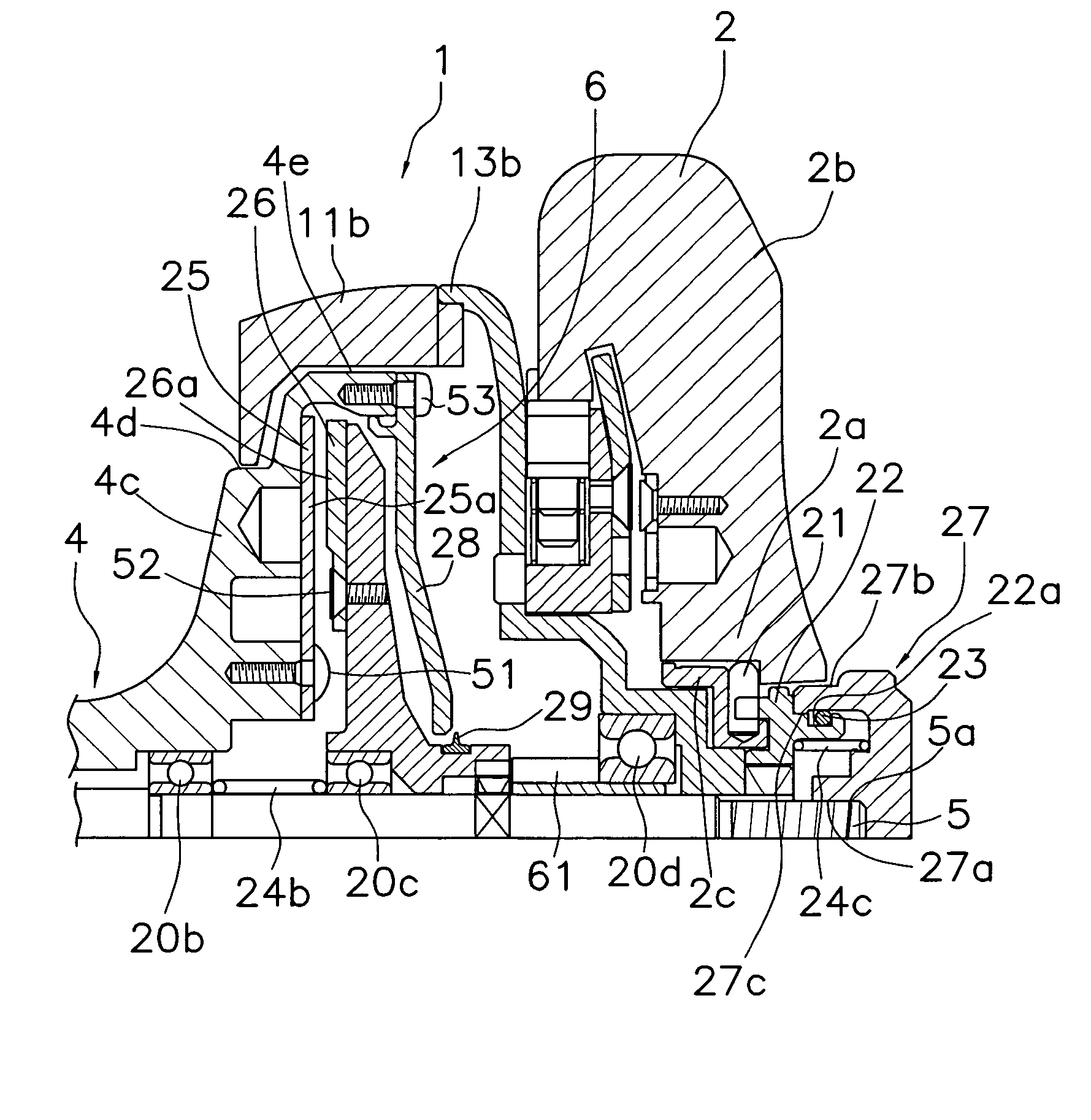
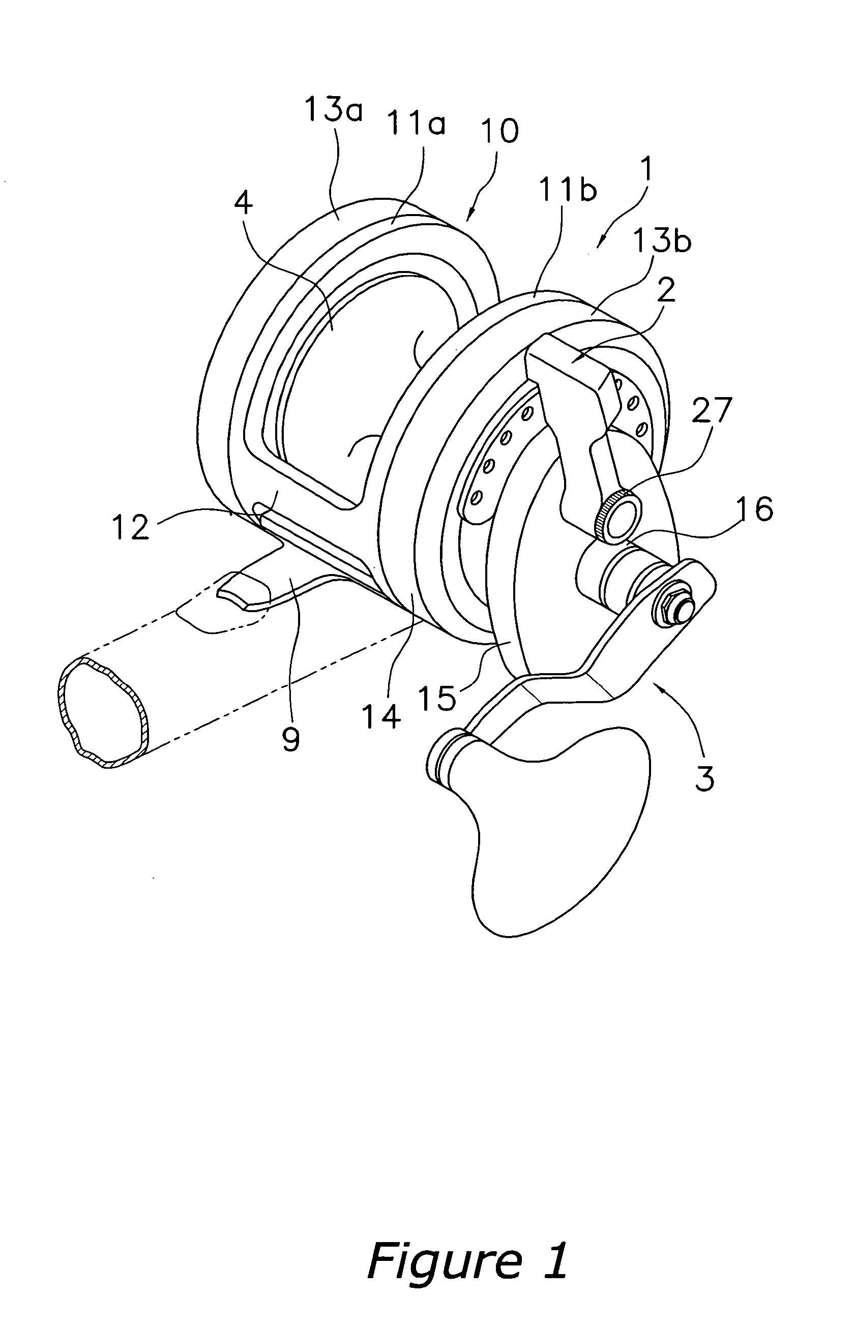
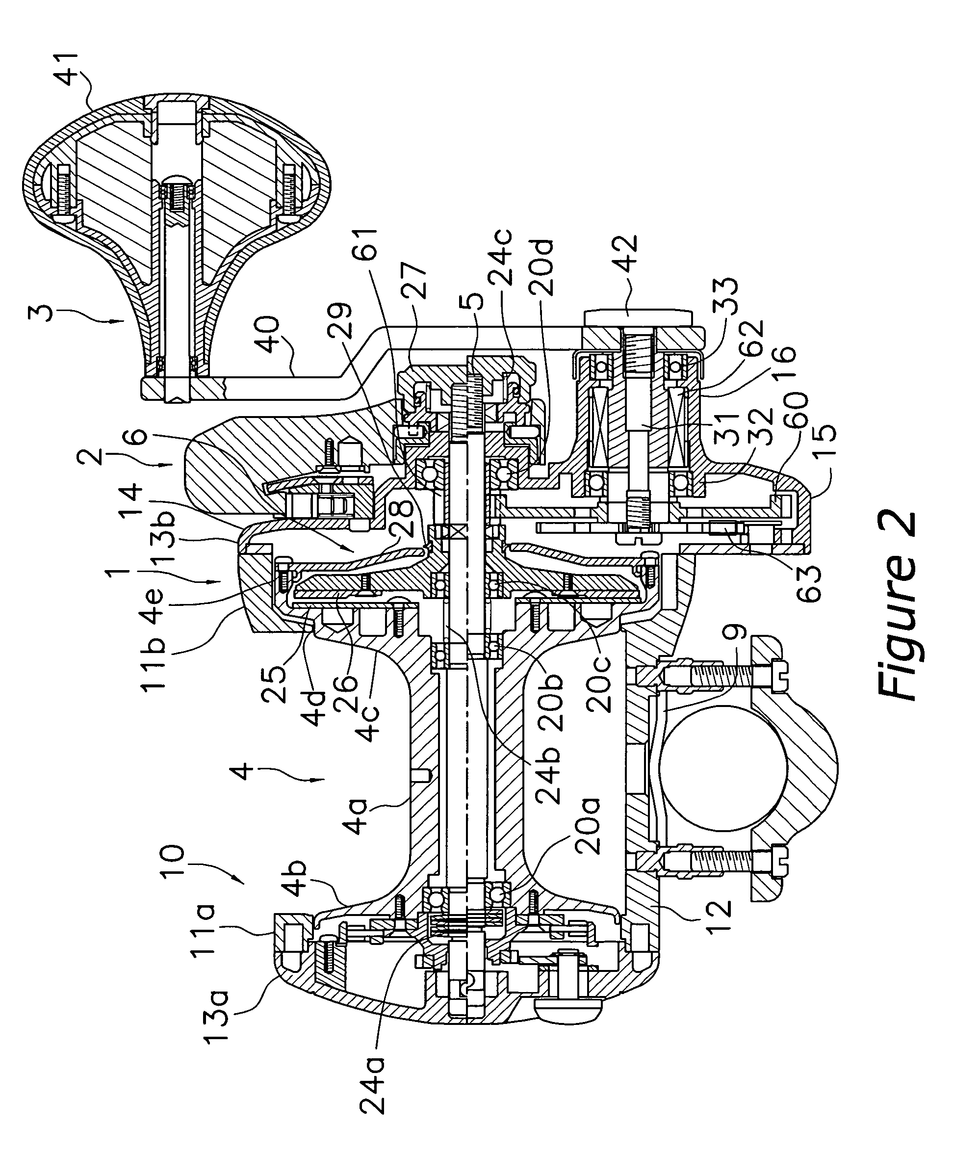
[0031] As shown in FIG. 1 and FIG. 2, a dual bearing reel according to one embodiment of the present invention is a mid-sized lever drag type, and includes a reel unit 1, a drag operation member 2 pivotably disposed on a side of the reel unit 1, a handle 3 rotatively supported on the reel unit 1 below the drag operation member 2, and a spool 4 disposed in the interior of the reel unit 1.

[0032] The reel unit 1 has a frame 10, and a first side cover 13a and a second side cover (an example of the first side of the reel unit) 13b that cover both sides of the frame 10. The frame 10 has a first side p...


PUM


Abstract

A drag mechanism has a drag operation member, a first cam member that is arranged on the inner peripheral portion of the drag operation member, a second cam member that is disposed opposite the first cam member, a drag adjustment member that is relatively rotatably mounted on the second cam member, a retaining member that retains the drag adjustment member in the axial direction relative to the second cam member, first and second urging members that urge the spool axially toward the drag operation member, a first brake member that is fixedly attached to the spool, and a second brake member that is movable in the axial direction of the spool shaft relative to the reel unit when at least one of the drag operation lever and the drag adjustment member is pivoted. Attachment and removal of the cam member can be performed easily.

Description

BACKGROUND OF THE INVENTION [0001] 1. Field of the Invention [0002] The present invention relates to a drag mechanism of a dual bearing reel. More particularly, the present invention relates to a drag mechanism of a dual bearing reel in which the braking force applied to the rotation of a spool in the line releasing direction changes, the spool is mounted on a spool shaft so as to be immovable in the axial direction and relatively rotatable, and the spool shaft is supported on a reel unit of the dual bearing reel so as to be immovable in the axial direction but relative unrotatable. [0003] 2. Background Information [0004] Lever drag type dual bearing reels that move the spool shaft in the axial direction with a lever shaped drag operation member to brake the spool are generally known as dual bearing reels. Such dual bearing reel includes a reel unit having a pair of side plates and side covers, a spool shaft that is supported on the reel unit so as to be movable in the axial directi...

Claims


Application Information

Patent Timeline
IPC IPC(8): A01K89/015A01K89/02A01K89/033
CPCA01K89/033A01K89/015
Inventor IKUTA, TAKESHIKAWASAKI, KEN'ICHI
Owner SHIMANO INC
Why Eureka
Try Eureka