Integrated blower for cooling device

a cooling device and integrated technology, applied in the direction of piston pumps, magnetic circuit rotating parts, magnetic circuit shapes/forms/construction, etc., can solve the problems of requiring improved systems for heat removal, premature device failure, and large power supplies and auxiliary components that generate increased amounts of heat, so as to improve blower performance and reduce sound level , the effect of improving the blower efficiency

Inactive Publication Date: 2006-01-12
INDAL DESIGN LAB
View PDF6 Cites 22 Cited by
  • Summary
  • Abstract
  • Description
  • Claims
  • Application Information

AI Technical Summary

Benefits of technology

[0011] Accordingly, it is an object of the present invention to provide an integrated blower for electronic device, which is capable of significantly improving of blower performances such as decreased sound level and increased blower efficiency.

Problems solved by technology

Cooling is important because if left unchecked, heat can cause electronic devices to malfunction during use or lead to premature device failure.
Additionally, improved processors require larger power supplies and auxiliary components that generate increased amounts of heat and require improved systems for heat removal.
The trend toward smaller and thinner electronic devices having larger, faster processors renders the traditional heat removal cooling systems inadequate for several reasons.
By this reason, the thermal efficiency of this heat dissipation device is insufficient.
However, such arrangement cause a vibration of the flat stator and magnetized rotor due to a rise of oscillation forces in a direction perpendicular to the planes of the flat stator and the magnetized rotor.
In one's turn the vibration generates an increasing sound level thus contradicts with modern requirements for cooling devices.
On the other hand mentioned vibration cause an energy losses thus decrease the motor efficiency of the electric drive and, correspondingly, a blower efficiency.

Method used


Image

  • Integrated blower for cooling device
  • Integrated blower for cooling device
  • Integrated blower for cooling device

Examples


Embodiment Construction

[0034] Preferred embodiment of the present invention will be described in detail below with reference to the accompanying drawings.

[0035]FIGS. 1-12 show an embodiment of the present invention.

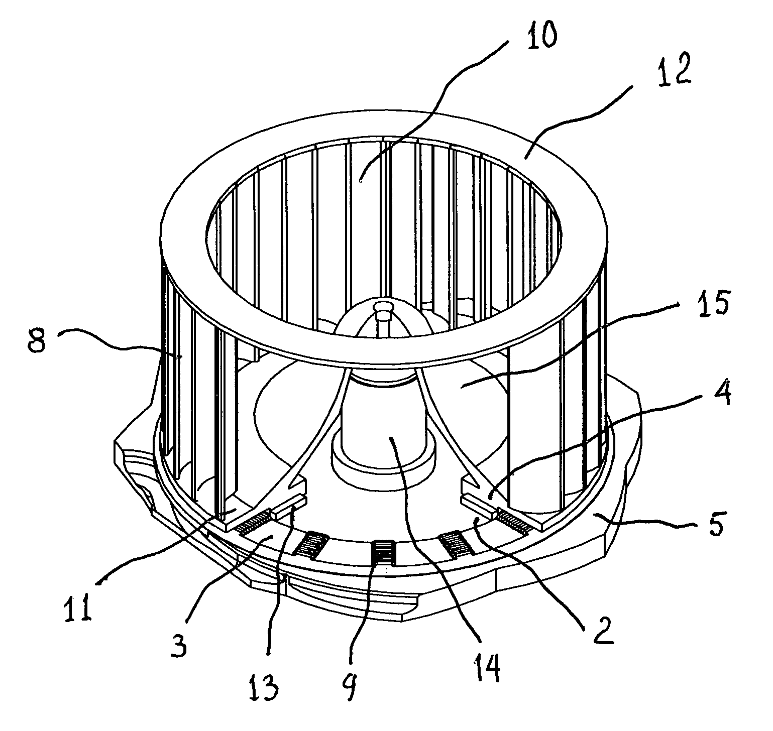
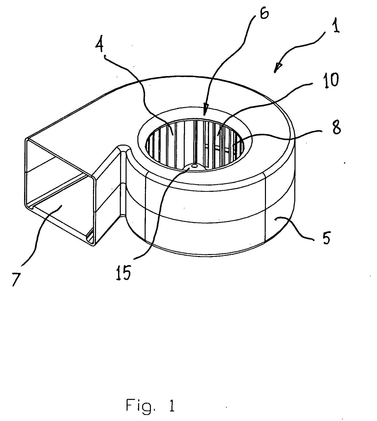
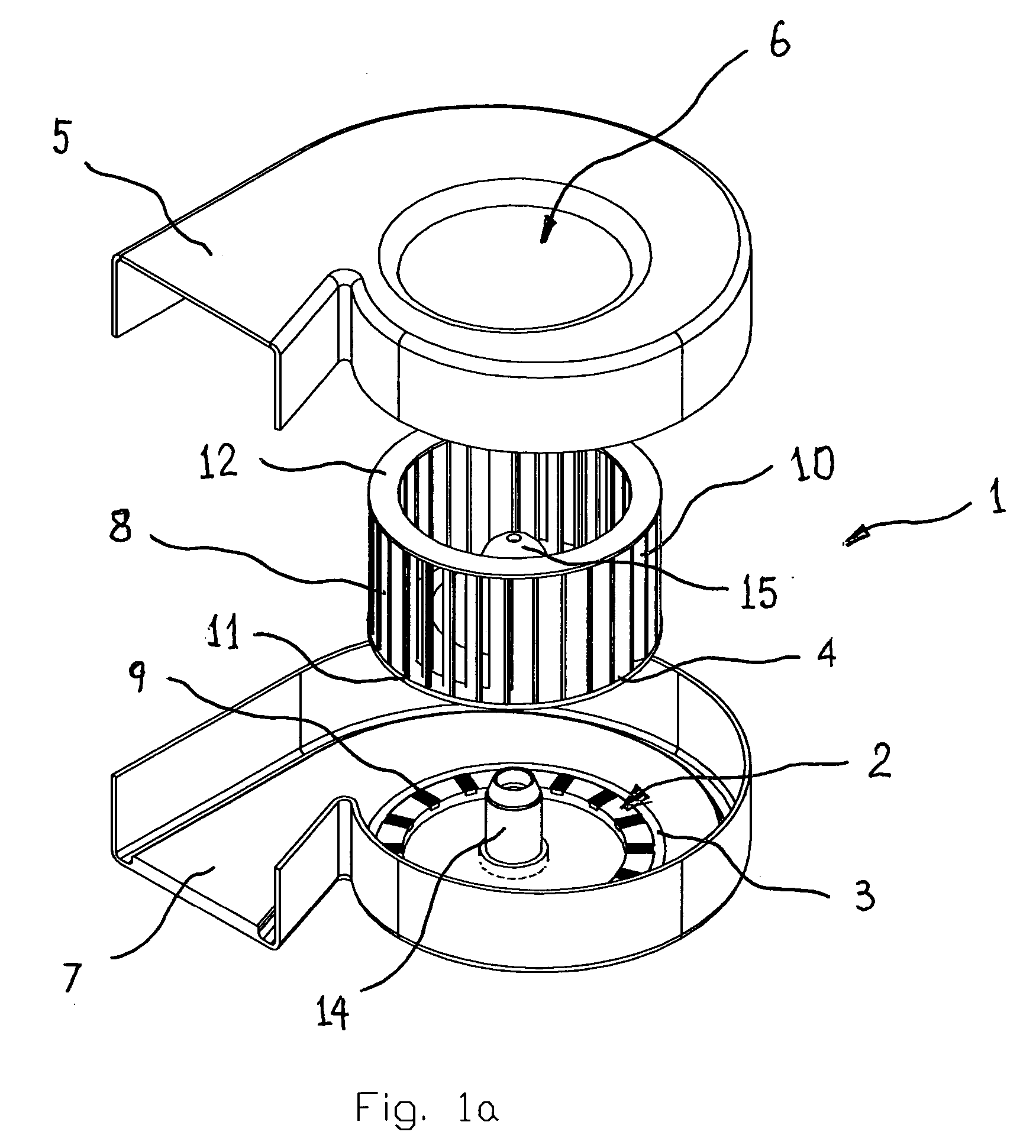
[0036] The integrated blower 1 for cooling device (FIGS. 1, 1a, 2, 3, 10 and 11) comprises an electric drive 2 with at least one set of a flat stator 3 and a magnetized rotor 4, a casing 5 with an inlet 6 and an outlet 7, and radial impeller 8. The flat stator 3 integrated with the casing 5 (FIG. 4) thus the flat stator 3 serving as at least a part of the casing 5, and the magnetized rotor 4 integrated with the radial impeller 8. The flat stator 3 comprises circumferential arrayed coils 9 with magnetic axes being coincide with a plane of the flat stator 3. The radial impeller 8 comprises blades 10 attached to a backplate 11 and a shroud 12, and circumferential arrayed magnetic means 13 thus serving as the magnetized rotor 4. The magnetic means 13 placed and magnetized along the plane of the f...


PUM


Abstract

An integrated blower for cooling device comprises an electric drive with at least one set of a flat stator and a magnetized rotor, a casing with an inlet and an outlet, and radial impeller. The flat stator integrated with the casing thus the flat stator serves as at least a part of the casing, and the magnetized rotor integrated with the radial impeller. The flat stator comprises circumferential arrayed coils with magnetic axes coincide with a plane of the flat stator. The radial impeller comprises blades attached to a backplate and a shroud, and circumferential arrayed magnetic means thus serve as the magnetized rotor. The magnetic means placed and magnetized along the plane of the flat stator thus magnetic axes of the coils and the magnetic means located at one plane substantially.

Description

CROSS REFERENCE TO RELATED APPLICATIONS [0001] The present application claims the benefit of priority of U.S. Provisional Patent Application No. 60 / 586,128, filed Jul. 7, 2004 for Edward Lopatinsky at al. the entire content of which is incorporated herein by reference.FIELD OF THE INVENTION [0002] The present invention relates generally to radial type impeller blowers for cooling of electronic devices. More particularly, the present invention relates to relative thin blowers. The present invention is particularly, but not exclusively, useful for cooling systems for regulating the temperature of electronic components of blade servers. BACKGROUND OF THE INVENTION [0003] The regulation of the temperature due to heat generated inside the housing of an electronic device is an important consideration during the design of an electronic device. Cooling is important because if left unchecked, heat can cause electronic devices to malfunction during use or lead to premature device failure. As ...

Claims


Application Information

Patent Timeline
Patent Type & Authority Applications(United States)
IPC IPC(8): H02K9/00H02K11/00F01D11/00
CPCF04D25/066H02K7/14H02K21/22H02K21/16H02K21/12
Inventor LOPATINSKY, EDWARDFEDOSEYEV, LEV
Owner INDAL DESIGN LAB
Why Eureka
Try Eureka