Flexographic pringting plate, flexographic printing device, production method for flexographic printing plate and production method for printing matter

a technology of printing plate and printing plate, applied in the field of flexographic printing plate, can solve the problems of frequently generated printed substances and reduce the inclination of the printing plate, and achieve the effect of minimizing the residue of printed substances and reducing the inclination

Inactive Publication Date: 2006-01-26
HITACHI PLANT TECH LTD +2
View PDF4 Cites 13 Cited by
  • Summary
  • Abstract
  • Description
  • Claims
  • Application Information

AI Technical Summary

Benefits of technology

[0020] A flexographic printing plate according to the present invention includes a raised part for transferring a printing substance to a printing substrate, the raised part having a top surface and a side, the top surface and the side forming an angle of not less than 90

Problems solved by technology

A ball, one of the problems in a printed substa

Method used


Image

  • Flexographic pringting plate, flexographic printing device, production method for flexographic printing plate and production method for printing matter
  • Flexographic pringting plate, flexographic printing device, production method for flexographic printing plate and production method for printing matter
  • Flexographic pringting plate, flexographic printing device, production method for flexographic printing plate and production method for printing matter

Examples


first embodiment

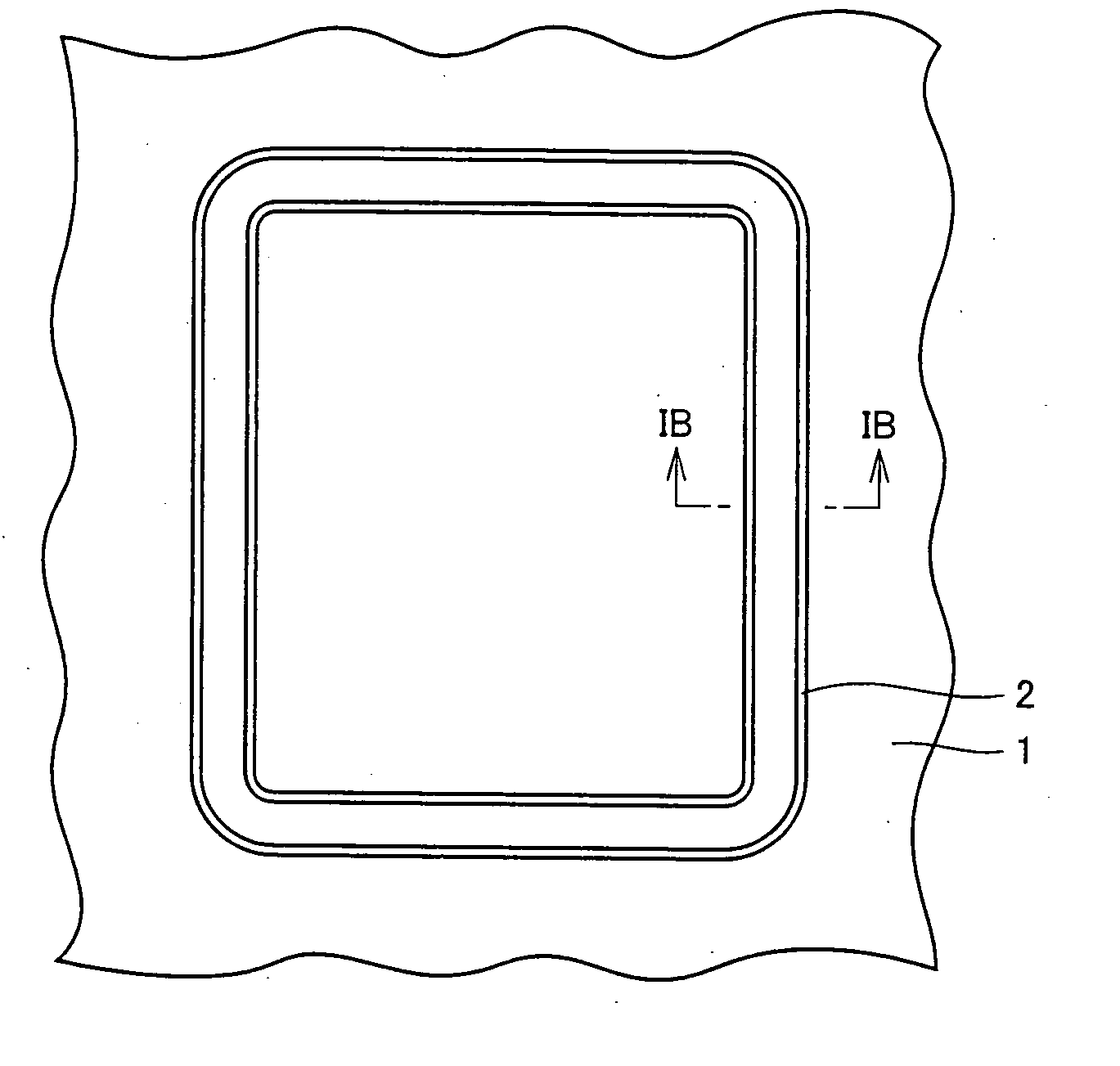
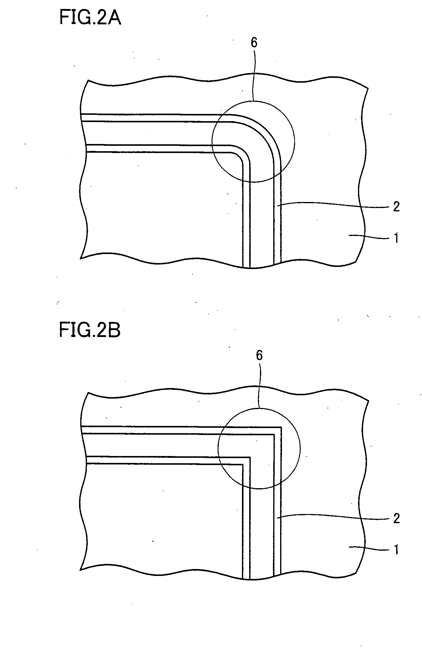
[0041] Referring to FIGS. 1A to 2B, a flexographic printing plate according to a first embodiment of the present invention will be described.

[0042] A flexographic printing plate is a relief printing plate in a flexographic printer for transferring a substance such as ink. FIGS. 1A and 1B show a flexographic printing plate according to the first embodiment of the present invention. FIGS. 1A and 1B show one raised part formed on a flexographic printing plate, of which FIG. 1A is a plan view and FIG. 1B is a cross sectional view in the direction of the arrow of IB-IB in FIG. 1A. Flexographic printing plate 1 has a raised part 2 on a major surface, where raised part 2 according to the present embodiment is shaped as a line when viewed from above and is in the shape of a near-quadrangular frame. The corners of the near-quadrangle are arced. Raised part 2 has a trapezoidal cross section as shown in FIG. 1B, and is constructed such that the shorter one of the two parallel sides forms the ...

second embodiment

[0051] Referring to FIGS. 3 to 15, a method of manufacturing a flexographic printing plate according to a second embodiment of the present invention will be described. FIGS. 3 to 15 show various steps in cross sectional views.

[0052] In FIG. 3, a first photosensitive resin layer 20 with a thickness of 1 mm is formed on a major surface of a lower device glass 25 mounted on an exposure device. First photosensitive resin layer 20 is an acrylic-based photosensitive resin. Next, as shown in FIG. 4, a base film 22 is placed on the upper surface of first photosensitive resin layer 20. Base film 22 is a sheet made of PET, although it may be substituted by a sheet of any other material that has no irregularities on its surface and is transmissive to ultraviolet light. As shown in FIG. 5, an upper device glass 26 is placed on the upper surface of base film 22 such that first photosensitive resin layer 20 and base film 22 are sandwiched by the two glasses of the exposure device.

[0053] First p...


PUM


Abstract

A flexographic printing plate includes a raised part (2) for transferring a printing substance to a printing substrate, the raised part (2) having a top surface and a side, the top surface and the side forming an angle of not less than 90° and not more than 105°. More preferably, the top surface and the side form an angle of not less than 95° and not more than 100°. A flexographic printer includes a flexographic printing plate as described above.

Description

TECHNICAL FIELD [0001] The present invention relates to a flexographic printing plate mounted on a flexographic printer. Further, the present invention relates to a flexographic printer. BACKGROUND ART [0002] Flexography is a type of relief printing that uses a flexographic plate of flexible rubber or resin, and a liquid printing substance. Currently, printing substrates (note that a printing substrate is understood as any object on which printing is performed) that can be used for printing with this method include paper as well as cellophane and aluminum foil and the like. [0003]FIG. 16 illustrates a printing unit that constitutes a key component of a flexographic printer. The printing unit includes an impression table 11 that supports a printing substrate 10, a flexographic printing plate 1 having a raised part 2, a plate cylinder 12, an anilox roll 16, a dispenser 18, and a doctor roll 15. Printing substance 17 such as ink is supplied to anilox roll 16 using dispenser 18. Anilox ...

Claims


Application Information

Patent Timeline
IPC IPC(8): B41N1/00G03F7/00B41C1/02B41C1/10B41M1/04B41N1/12G03F7/095G03F7/20G03F7/38
CPCB41C1/025B41C1/10B41C1/1083B41M1/04G03F7/2032G03F7/0955G03F7/2012G03F7/2022B41N1/12B41N1/04G03F7/00
Inventor SAAI, YUJIKIRA, TAKATOSHIMORIMOTO, MITSUAKINAKAHARA, MAKOTOKAWABE, SHINICHIROKOMURA, YUICHISAITO, YOSHIMI
Owner HITACHI PLANT TECH LTD
Why Eureka
Try Eureka