Top loading fixed line trimmer head

a fixed line and trimmer head technology, applied in metal working apparatus, agriculture tools and machines, agriculture, etc., can solve the problems of not always taking place, the line feeding from the hub, and the wound line tends to get stuck, so as to facilitate the rapid removal of the line and facilitate the loading of the lin

Inactive Publication Date: 2006-03-16
PHILIPS ROBERT L 50
View PDF3 Cites 13 Cited by
  • Summary
  • Abstract
  • Description
  • Claims
  • Application Information

AI Technical Summary

Benefits of technology

[0012] It is an additional object of this invention to provide an improved fixed line trimmer head for string trimmer machines in which the line is simple to install and replace.
[0014] It is a further object of this invention to provide a top loading fixed line trimmer head for string trimmer machines which is easy to load with trimmer lines, and which employs locations of line exit openings and line termination apertures designed to firmly hold the line in place during use, and to facilitate rapid removal of line which is to be replaced.

Problems solved by technology

A problem exists, however, with bump-and-feed trimmers in that frequently the line which is wound tends to become stuck, either due to partial fusion of the line within the hub, caused by high frequency vibration, or by successive turns of the line wound on the hub becoming somewhat entangled.
As a result, feeding of the line from the hub, when desired, does not always take place.
This is a time consuming and frustrating experience for many users of flexible line string trimmers.
This is awkward and the machine is heavy to hold.
In addition, because of the inverted position of the machine, the possibility of gasoline spillage is ever present.
Bottom loading machines also preclude the utilization of replaceable ground spacers of different heights, since such ground spacers need to be attached to the underside of the head.
Another disadvantage, particularly with commercial machines, is that the heavy duty line which is used is difficult to bend and load into the machines.
The sharp bends which are required for insertion of the line make both insertion of a new line and removal of a depleted line difficult, particularly when the larger sizes of line mentioned above are used with such a machine.
The Fogle head, however, requires loading and replacement of the line from the bottom or underside of the head, thus causing it to be subject to the disadvantage of awkward bottom loading, for the reasons discussed above.

Method used


Image

  • Top loading fixed line trimmer head
  • Top loading fixed line trimmer head
  • Top loading fixed line trimmer head

Examples


Embodiment Construction

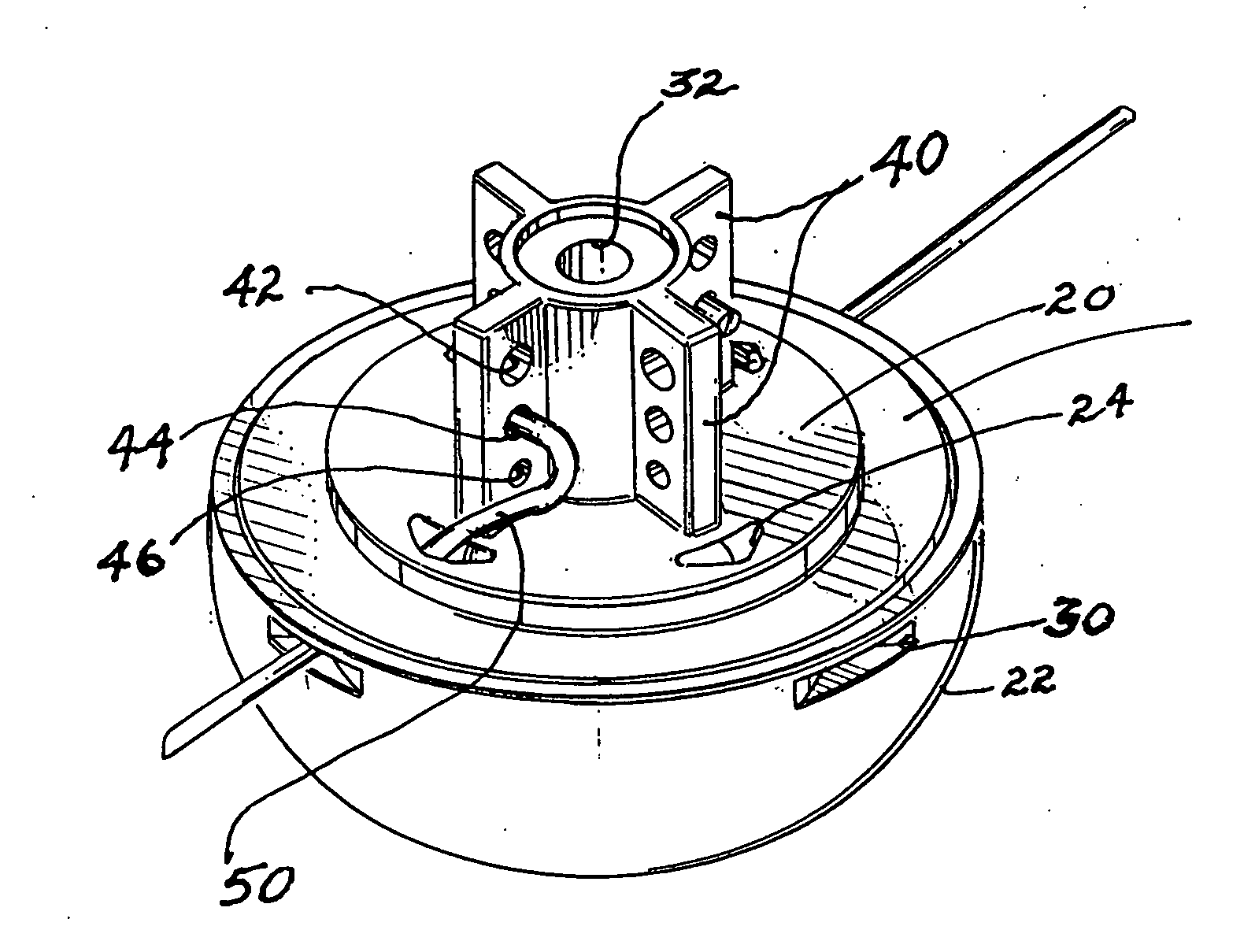
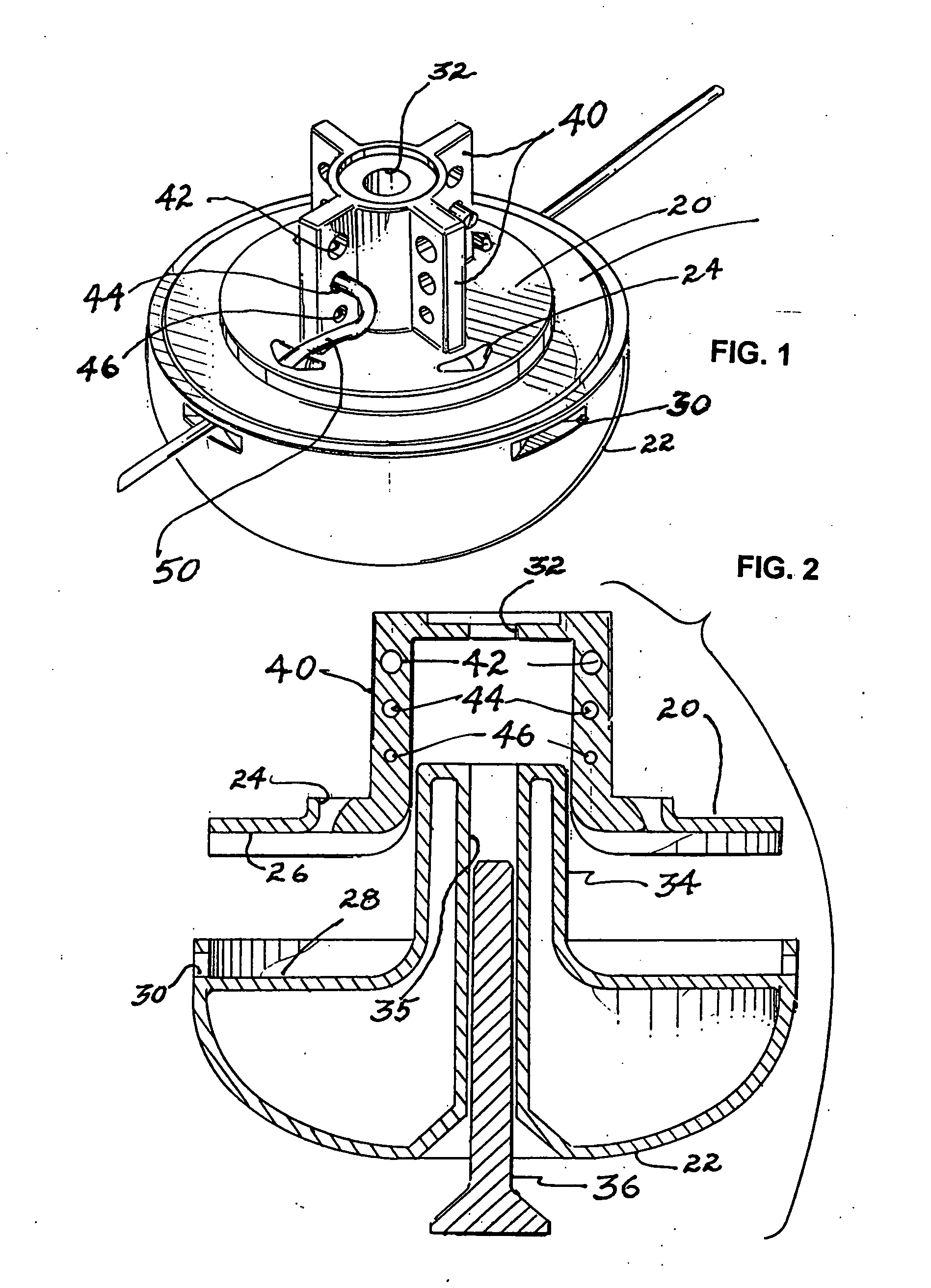
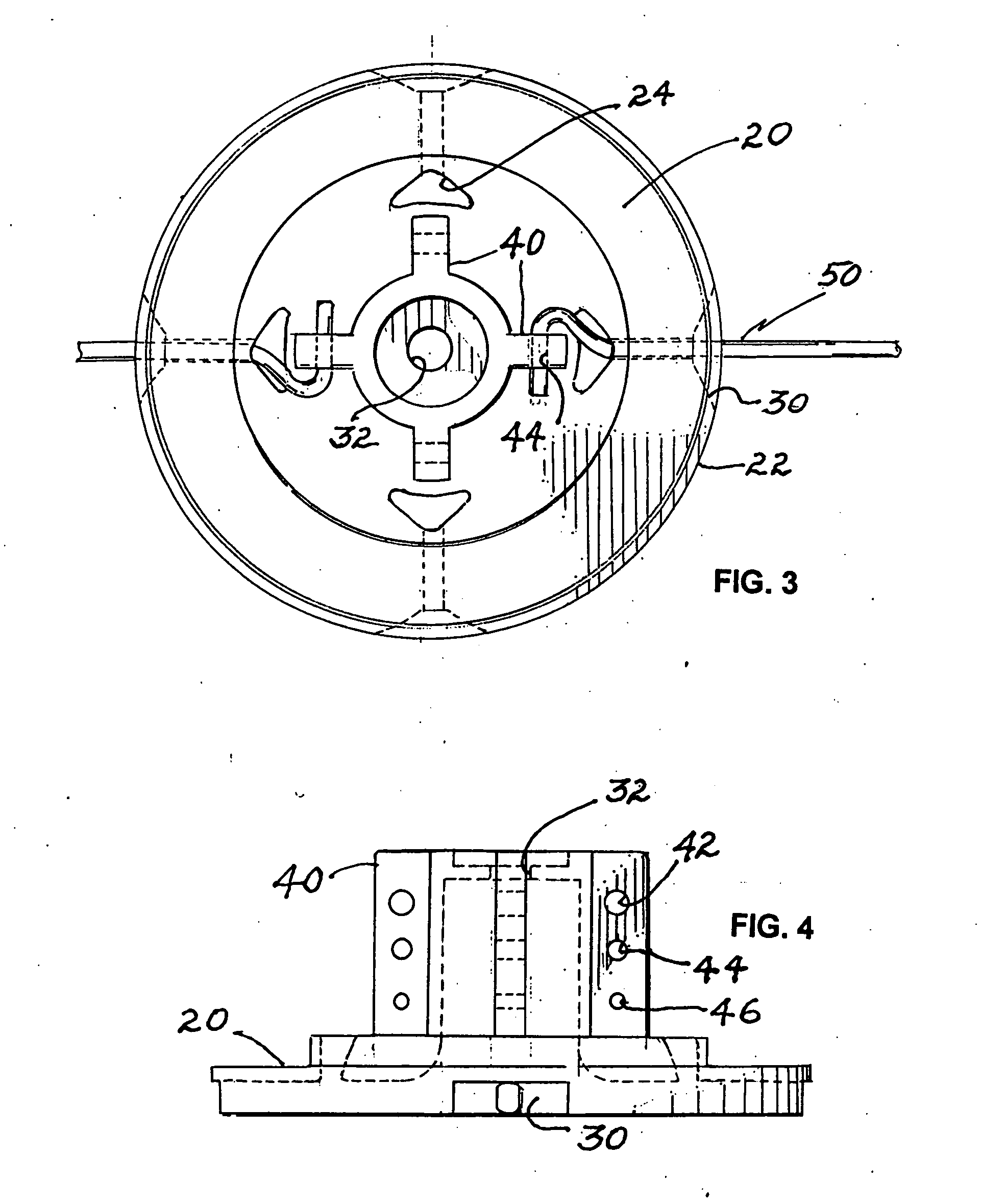
[0031] Reference now should be made to the drawings, in which the same reference numbers are used throughout the different figures to designate the same or similar components. FIGS. 1 through 4 are directed to a preferred embodiment of the invention as applied to a top-loading, fixed length line trimmer head for a string trimmer machine. The trimmer head which is illustrated in FIGS. 1 through 4 may be used in conjunction with either a hand-held trimmer or a high-wheeled brush trimmer. The principles of operation of the head are identical in either application.

[0032] In the embodiment shown in FIGS. 1 through 4, the trimmer head itself comprises an upward extending central cylindrical hub terminating at its lower end in a circular flange 20. The hub itself has a central aperture 32 located in it for receiving a bolt 36 (FIG. 2), which is threaded upwardly through the opening 32 to attach the trimmer head to the drive shaft mechanism of a hand held trimmer or a high wheeled trimmer....


PUM


Abstract

A fixed line top-loading trimmer head for string trimmer machines, uses line segments of a predetermined length. The head has a central hub designed for attachment to the drive shaft of a string trimmer machine. A circular flange is attached to, and extends outwardly from, the central hub. This circular flange has one or more trimmer line exit openings on the circumference. The hub, located above the upper surface of the circular flange, is provided with either line termination apertures in the form of holes or channels which are angularly offset from the exit openings in the circular flange; or it is provided with an offset guide channel through which a trimmer line is passed between the exit openings. A line guide channel is located in the flange between the line exit openings and the line termination apertures, or the offset channel on the hub, for guiding line between the exit openings and the offset channel or termination apertures.

Description

BACKGROUND [0001] Weed and grass trimmers have been developed which employ a rotatable hub, with a short length of flexible nylon or other plastic line extending from the hub. When the hub is rotated (typically, at speeds from 6,000 RPM to 12,000 RPM), the tip of the line extending from the hub provides the cutting or trimming action. Weed and grass trimmers using this principle of operation have become popular for their versatility of use, and because the flexible trim line is safer to use than rigid rotating steel blades. [0002] Various types of devices have been developed for using such trimmer lines. Typically, rotating line trimmers or rotating string trimmers employ a line which generally has a circular cross section. In many hand-held trimmers, the line is wound on a storage reel in the hub of the device, and is fed out of a hole in the hub in discrete amounts, as the end wears off or breaks off. Trimmers of this type sometimes are referred to as “bump-and-feed” trimmers, sin...

Claims


Application Information

Patent Timeline
Patent Type & Authority Applications(United States)
IPC IPC(8): B26B7/00A01D34/416
CPCA01D34/416
Inventor FOGLE, JOHN R.
Owner PHILIPS ROBERT L 50
Why Eureka
Try Eureka