Display device and driving method

a technology of a display device and a driving method, which is applied in the direction of static indicating devices, instruments, etc., can solve the problems of ineffective change of the format of the video signal in each case, easy noise, and discontinuous display of images, so as to achieve easy switching, improve the aperture ratio, and improve the effect of image quality

Inactive Publication Date: 2006-04-20
SEMICON ENERGY LAB CO LTD
View PDF10 Cites 23 Cited by
  • Summary
  • Abstract
  • Description
  • Claims
  • Application Information

AI Technical Summary

Benefits of technology

[0056] According to the invention, a screen can be easily switched between the vertical direction and the ...

Problems solved by technology

However, it is not effective to change the format of the video signals in each case, since switching of the display device between the display in the vertical direction and the display in the horizontal direction is preferably performed with flexibility.
If data is switched between the vertical direction and the horizontal direction using the frame memory as described above, however, there is ...

Method used


Image

  • Display device and driving method
  • Display device and driving method
  • Display device and driving method

Examples


embodiment 1

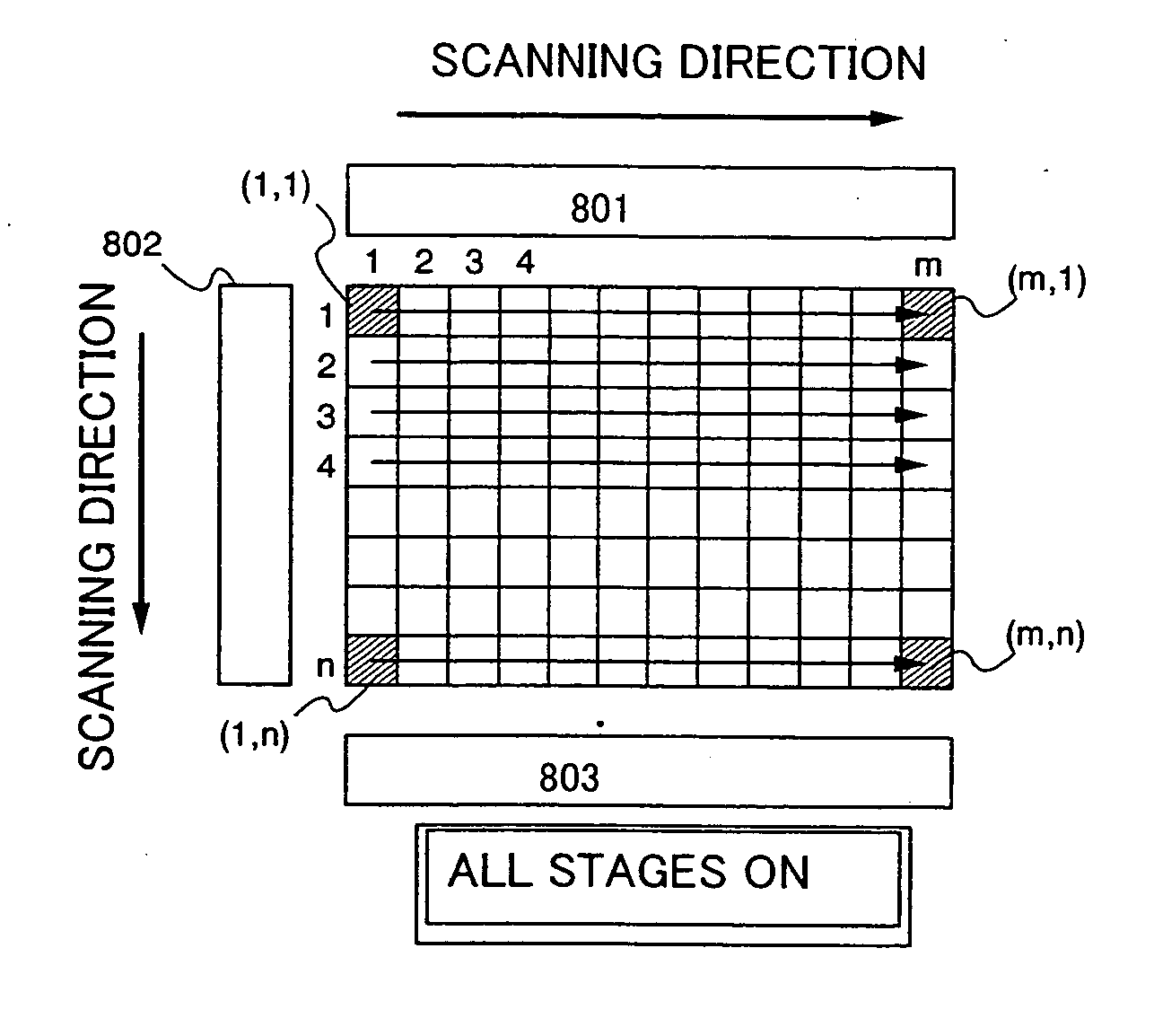
[0096] In the case of switching between the display in the vertical direction and the display in the horizontal direction in the manner shown in Embodiment Mode, the scanning direction of the first gate signal line driver circuit is focused on. In the normal display, as shown in FIG. 8A, the first gate signal line driver circuit sequentially selects and scans gate signal lines from the first row to the n-th row. Meanwhile, when the screen is switched between the vertical direction and the horizontal direction, as shown in FIG. 8B, the first gate signal line driver circuit sequentially selects and scans gate signal lines from the n-th row to the first row. Thus, when switching between the display in the vertical direction and the display in the horizontal direction, the scanning direction of the first gate signal line driver circuit is required to be changed.

[0097]FIG. 9 shows a configuration of a driver circuit added with a scanning direction switching circuit. A shift register 902...

embodiment 2

[0099] This embodiment shows an example of easily switching between the display in the vertical direction and the display in the horizontal direction in a different manner than Embodiment Mode.

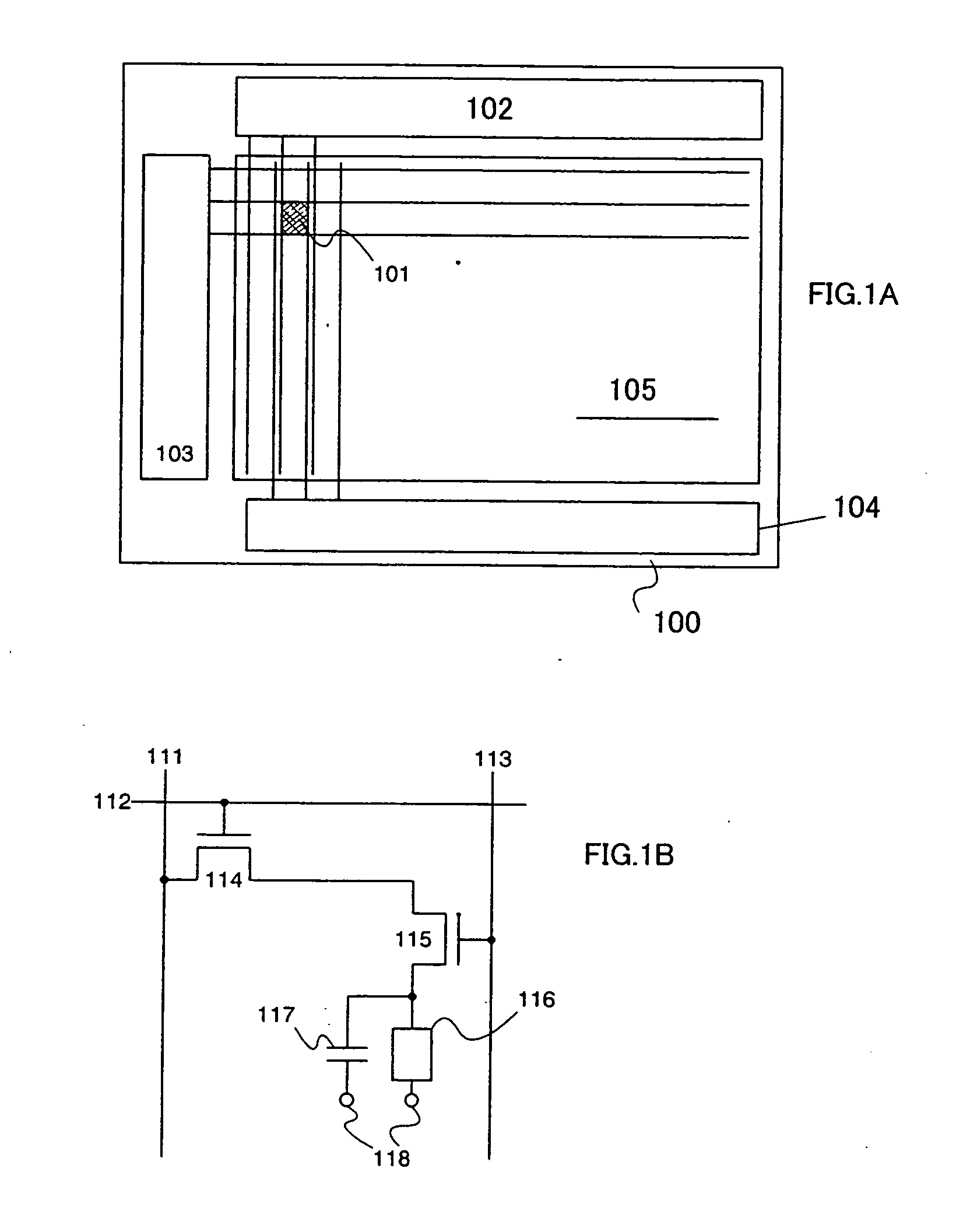
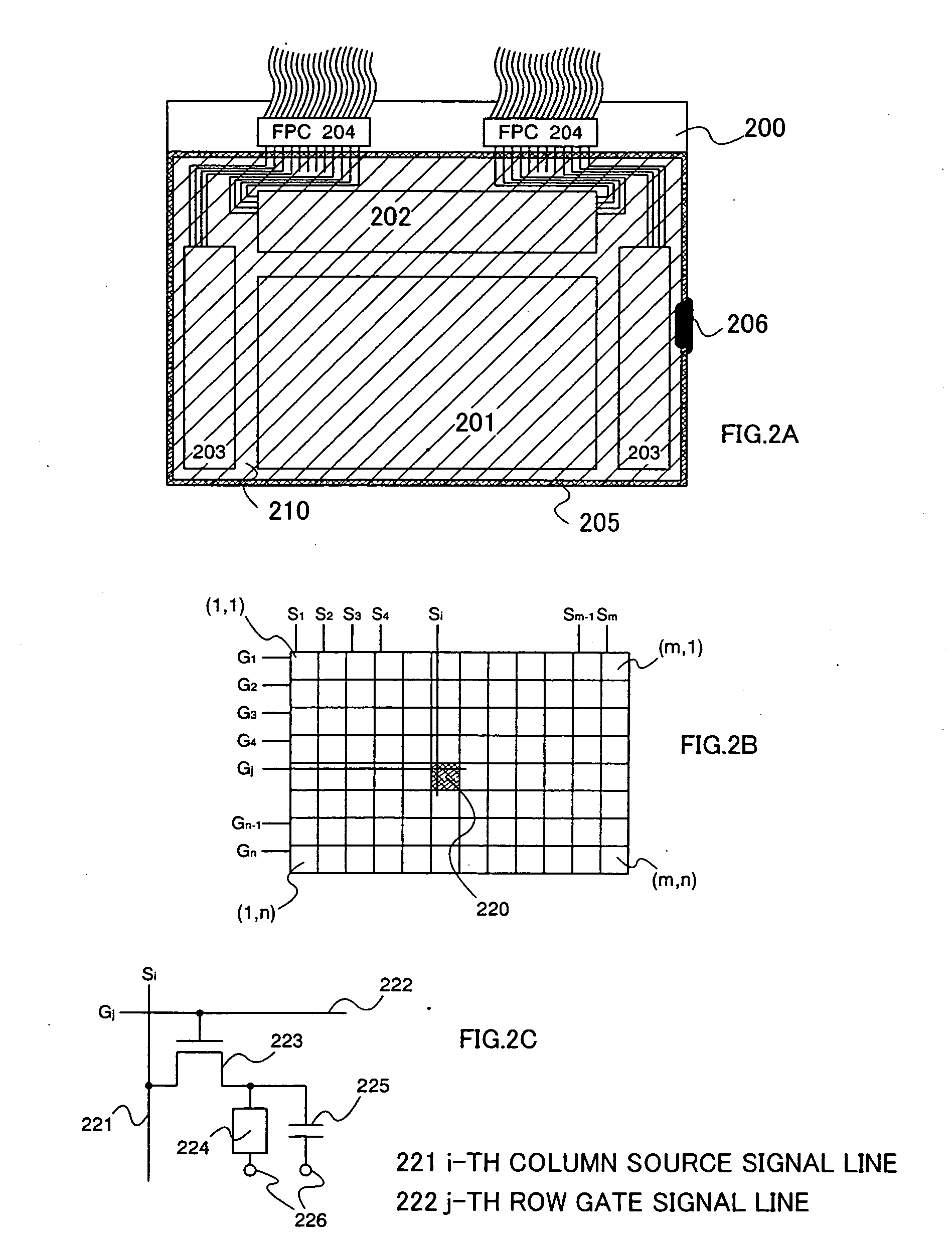
[0100]FIG. 12A shows a configuration of a display device. A pixel portion 1206 is formed over a substrate 1200. In addition, a first source signal line driver circuit 1202, a first gate signal line driver circuit 1203, a second source signal line driver circuit 1204, and a second gate signal line driver circuit 1205 are formed over the substrate 1200. In this configuration, the scanning direction of the first source signal line driver circuit is perpendicular to that of the second source signal line driver circuit. Similarly, the scanning direction of the first gate signal line driver circuit is perpendicular to that of the second gate signal line driver circuit.

[0101] Reference numeral 1201 denotes one pixel in the pixel portion 1206, the configuration of which is shown in FIG. 12B. The pix...

embodiment 3

[0105] In a display device with a large screen and high resolution, it is necessary to drive as many pixels as possible during a predetermined period. The driving frequency increases according to the conventional driving method; therefore, a division driving is adopted in many cases.

[0106]FIG. 14 shows a configuration example of a source signal line driver circuit in the case of performing the division driving, which has a shift register 1402 including a plurality of stages of flip flops 1401, a NAND 1403, a buffer 1404, a sampling switch 1405, and the like.

[0107] A video signal is written to one pixel by one sampling pulse in the circuit shown in FIG. 6A. Meanwhile, in the circuit shown in FIG. 14, four video signals are inputted in parallel and video signals are simultaneously written to four pixels by one sampling pulse. According to this, the driving frequency of the source signal line driver circuit can be reduced to 1 / the number of divisions as compared to the conventional d...


PUM


Abstract

A display device capable of switching a screen between a display in the vertical direction and a display in a horizontal direction. The scanning direction of a first gate signal line driver circuit is perpendicular to that of a source signal line driver circuit, and the scanning direction of a second gate signal line driver circuit is perpendicular to that of the first gate signal line driver circuit. In a normal display, the vertical scanning of a screen is performed by the first gate signal line driver circuit. Meanwhile, in the case of switching between the display in the vertical direction and the display in the horizontal direction, the vertical scanning of the screen is performed by the second gate signal line driver circuit. The screen is driven by a field sequential method and a pixel is not divided into RGB; therefore, switching of the display direction can be facilitated.

Description

BACKGROUND OF THE INVENTION [0001] 1. Field of the Invention [0002] The present invention relates to a display device where a pixel portion is formed using a liquid crystal element, and an electronic apparatus using such a display device for a display portion. In particular, the invention relates to a display device adopting a field sequential method, and an electronic apparatus using such a display device for a display portion. [0003] 2. Description of the Related Art [0004] In recent years, a display device where a semiconductor thin film is formed over an insulator such as a glass substrate, particularly an electronic circuit using a thin film transistor (hereinafter referred to as a TFT) has been used in various fields. In particular, the TFT is often used for a display device, and an active matrix display device typified by an LCD (Liquid Crystal Display) is widely used for many products. The active matrix display device using TFTs has hundreds of thousands to millions of pixel...

Claims


Application Information

Patent Timeline
IPC IPC(8): G09G3/36
CPCG09G3/3659G09G3/3677G09G2300/0426G09G2300/0491G09G2310/0235G09G2340/0492
Inventor KOYAMA, JUNYAMAZAKI, SHUNPEI
Owner SEMICON ENERGY LAB CO LTD
Why Eureka
Try Eureka