Plasma display apparatus and driving method thereof

a technology of a display apparatus and a driving method, which is applied in the direction of instruments, static indicating devices, etc., can solve the problems of increasing the discharge firing voltage, the size of the cell increases, and the discharge efficiency is not good, so as to increase the discharge efficiency, increase the electrode distance, and increase the amount of space charges

Inactive Publication Date: 2006-06-15
INTELLECTUAL DISCOVERY CO LTD
View PDF3 Cites 4 Cited by
  • Summary
  • Abstract
  • Description
  • Claims
  • Application Information

AI Technical Summary

Benefits of technology

[0017] According to the present invention, it is possible to increase discharge efficiency without rising of a driving voltage or increasing an electrode distance by increasing an amount of space charges by means of applying a negative pulse upon falling of a sustain pulse.

Problems solved by technology

Therefore, discharge efficiency is not good.
Therefore, because a space between a scan electrode and a sustain electrode increases to use a positive column area in the plasma display panel, there is a problem that a size of a cell increases.
In addition, there is a problem that a discharge firing voltage increases as a space between electrodes increases.
Therefore, if the distance d between electrodes increases to use a positive column area, there is a problem that a discharge firing voltage Vf also increases.

Method used


Image

  • Plasma display apparatus and driving method thereof
  • Plasma display apparatus and driving method thereof
  • Plasma display apparatus and driving method thereof

Examples


first embodiment

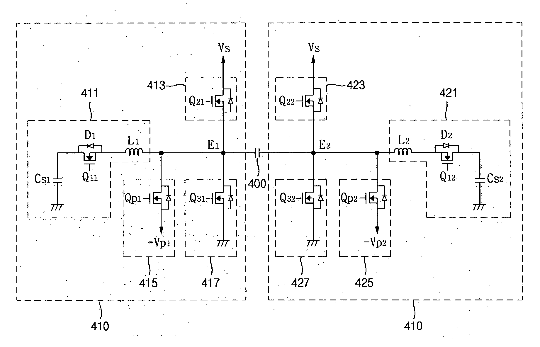
[0067] The first energy recovery unit 411 comprised in the plasma display apparatus according to the present invention comprises a first energy recovery capacitor (Cs1), a first supply switch (Q11), a first recovery diode (D1), and a first inductor (L1).

[0068] The first energy recovery capacitor (Cs1) stores the first energy which is supplied or recovered. The first energy stored in the first energy recovery capacitor (Cs1) corresponds to 0.5 times of the first positive voltage (Vs1).

[0069] The first supply switch (Q11) is turned on and forms a supply path of the first energy stored in the first energy recovery capacitor (Cs1). One terminal of the first supply switch (Q11) is connected to the first energy recovery capacitor (Cs1) and the other terminal of the first supply switch (Q11) is connected to one terminal of the first inductor (L1).

[0070] The first recovery diode (D1) comprises a cathode terminal commonly connected to one terminal of the first supply switch (Q11) and one t...

second embodiment

[0090] The first energy recovery unit 511 comprised in the plasma display apparatus according to the present invention comprises a first energy recovery capacitor (Cs1), a first supply switch (Qp-1), a first recovery switch (Qr-1), a first diode (D1), a second diode (D2), and a first inductor (L1).

[0091] The first energy recovery capacitor (Cs1) stores the first energy which is supplied or recovered. The first energy stored in the first energy recovery capacitor (Cs1) corresponds to 0.5 times of the first positive voltage (Vs1).

[0092] The first supply switch (Qp-1) is turned on and forms a supply path of the first energy stored in the first energy recovery capacitor (Cs1). One terminal of the first supply switch (Qp-L1) is connected to the first energy recovery capacitor (Cs1) and the other terminal of the first supply switch (Qp-1) is connected to one terminal of the first inductor (L1).

[0093] The first recovery switch (Qr-1) is turned on and forms a recovery path of the first en...

fourth embodiment

[0175] In a driving method of the plasma display apparatus according to the present invention, as many space charges are formed by supplying a negative peak pulse of a ramp form, an effect using a positive column area is obtained.


PUM


Abstract

There is provided a plasma display apparatus and a driving method of a plasma display panel. The plasma display apparatus comprises a plasma display panel comprising a first electrode and a second electrode, and an electrode driver alternatively applying a sustain pulse of a first polarity to the first electrode and the second electrode and applying a pulse of a second polarity opposite to a first polarity after a magnitude of a voltage of a sustain pulse of a first polarity is maximized. Therefore, it is possible to increase discharge efficiency without rising a driving voltage or increasing an electrode space by increasing an amount of space discharge.

Description

[0001] This Nonprovisional application claims priority under 35 U.S.C. §119(a) on Patent Application No. 10-2004-0105778 filed in Korea on Dec. 14, 2004 the entire contents of which are hereby incorporated by reference. BACKGROUND OF THE INVENTION [0002] 1. Field of the Invention [0003] The present document relates to a plasma display apparatus and a driving method thereof. [0004] 2. Description of the Background Art [0005]FIG. 1 is a view illustrating a discharge shape formed upon a regular glow discharge. An oblique line area shown in FIG. 1 is a bright area emitting a large amount of light. If a DC voltage of a predetermined magnitude or more is applied to a cathode electrode and an anode electrode, an inside of a discharge tube is divided into a cathode glow, a negative glow, a positive column, and an anode glow and emits light. [0006] At this time, because a light emitting amount of visible rays or ultraviolet rays in a negative glow area is larger than that of visible rays or ...

Claims


Application Information

Patent Timeline
Patent Type & Authority Applications(United States)
IPC IPC(8): G09G3/28G09G3/288G09G3/294G09G3/296
CPCG09G3/2942G09G3/2965G09G3/296
Inventor MOON, SEONG HAK
Owner INTELLECTUAL DISCOVERY CO LTD
Why Eureka
Try Eureka