Battery holder

a battery and holder technology, applied in the field of batteries, can solve the problems of not being particularly robust, buying a new entity comprising the battery and the cover, and being very expensive, so as to save production costs, protect the battery, and remove the part more robust

Inactive Publication Date: 2006-07-06
NOKIA TECHNOLOGLES OY
View PDF6 Cites 7 Cited by
  • Summary
  • Abstract
  • Description
  • Claims
  • Application Information

AI Technical Summary

Benefits of technology

[0014] It is further an advantage of the invention that the integration of battery module and battery holder makes the removable part more robust compared to a cover by itself. At the same time, the battery holder protects the battery from mechanical stresses, especially when the mechanical construction of the battery module itself is thin and weak. Nowadays, batteries usually do not comprise rigid plastic parts at both ends any more. Instead, they are often only covered with an adhesive tape.
[0015] It is equally an advantage of the invention that it enables to save costs in the production, since the battery module is assembled by the user. The invention also facilitates logistics and thus allows an increase in battery production. Moreover, a standard battery can be used for the battery module, while design based product variants can be made by varying the surface of the battery holder.
[0016] Preferred embodiments of the invention become apparent from the dependent claims.
[0017] The at least one battery can be combined with the battery module in any suitable manner.
[0018] Preferably, a battery is connected to a battery holder by sliding the battery along guiding elements provided on the battery holder. The dimensions of the receiving space defined by the guiding elements should be such that it is suitably tight to hold the battery.
[0019] The battery holder may comprise in addition locking means, which may fix the battery to the battery holder and / or adjust the size of the receiving space of the battery holder to a variable battery size.

Problems solved by technology

It might be considered a disadvantage by some users that the cover covering a battery which was inserted into a spacing provided in an electronic device is often very light, whereby its handling resembles to the handling of a toy.
Moreover, such a cover is usually not particularly robust.
This approach has the disadvantage, however, that whenever the battery has to be exchanged, the customer has to buy a new entity comprising the battery and the cover, which is rather expensive.

Method used


Image

  • Battery holder
  • Battery holder
  • Battery holder

Examples


Embodiment Construction

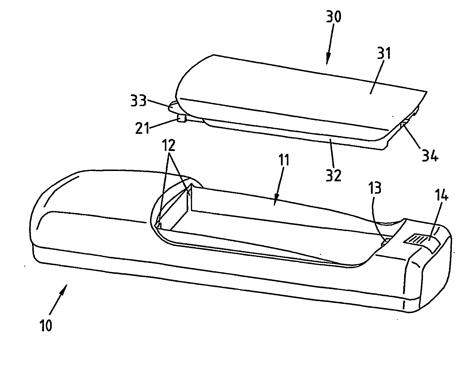
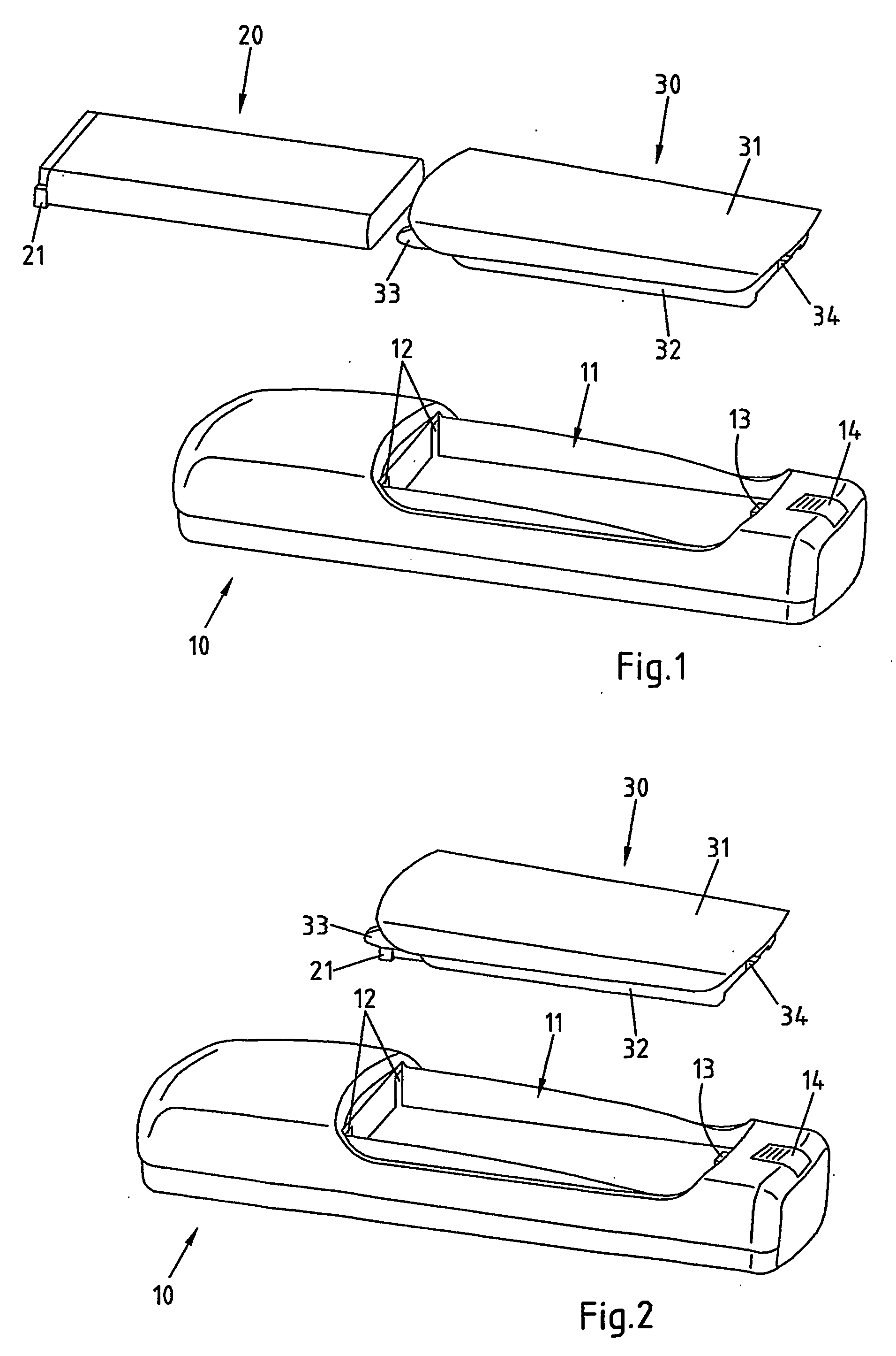
[0025]FIG. 1 presents a cover 10 forming part of an electronic device, a battery 20 and a battery holder 30, which are to be assembled. The electronic device, of which only cover 10 is shown, can be for example a mobile phone.

[0026] The battery module 20 is a standard battery module which comprises electrical contacts 21 at one end.

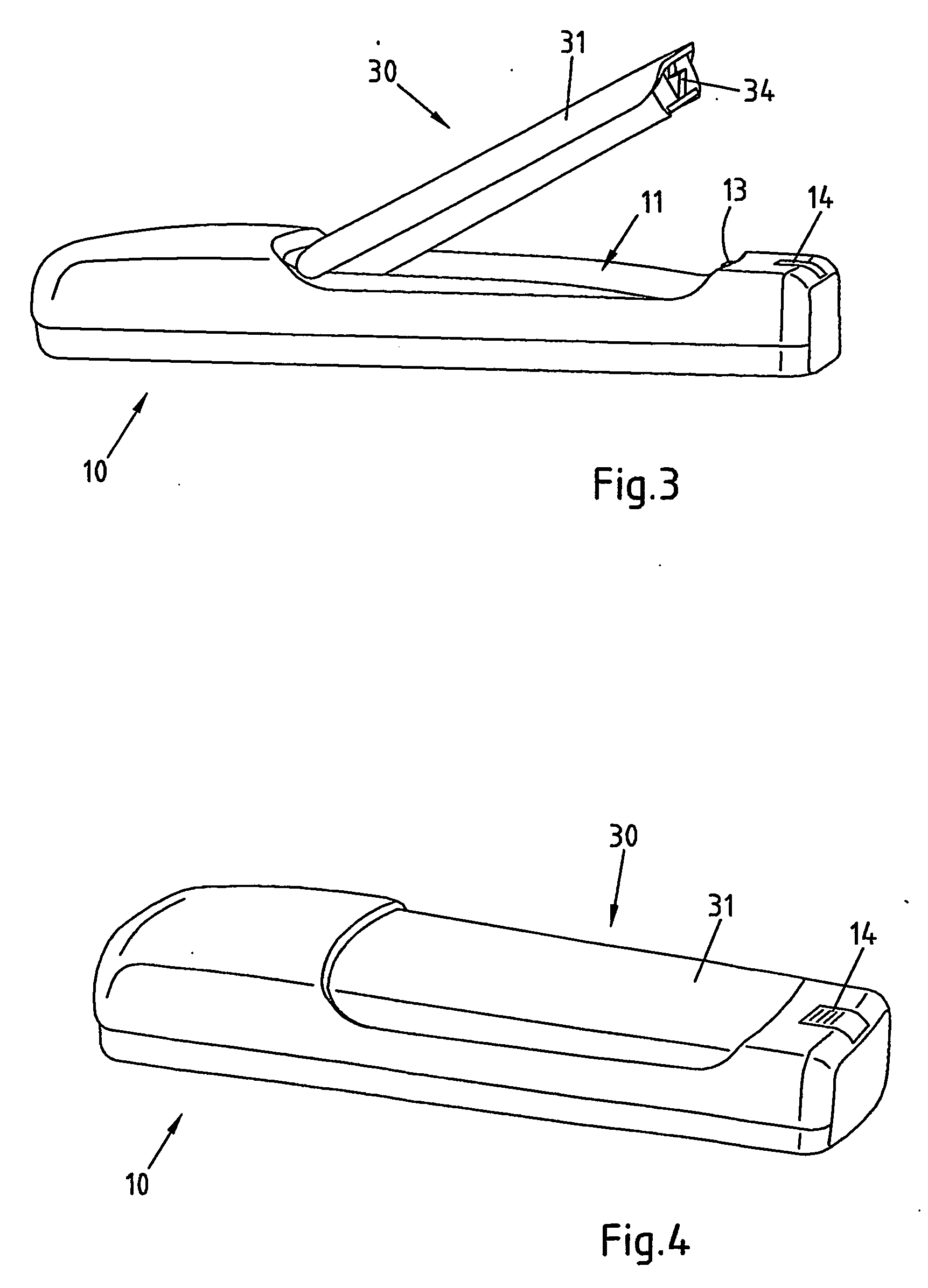
[0027] The battery holder 30 comprises a basically even surface 31 which has a length and width slightly larger than the length and width of the battery module 20.

[0028] At the opposite side, the battery holder comprises curved guiding elements 32 which are suited to receive the battery module 20 and to hold it in place. More specifically, the guiding elements 32 are suited to receive and guide the battery module 20 when it is slid lengthwise along the battery holder 30 at the side of the battery holder opposing the surface 31 of the battery holder 30. With the guiding elements 32, the battery holder 30 has a depth which is slightly larger than the dep...


PUM

PropertyMeasurementUnit
poweraaaaaaaaaa
electricalaaaaaaaaaa
life timeaaaaaaaaaa

Abstract

The invention relates to a battery holder 30 for an electronic device. In order to provide an improved possibility of exchanging a battery of an electronic device, it is proposed that the battery holder 30 comprises an outer surface 31, means 32 for receiving an exchangeable battery 20 and means 33, 34 for connecting the battery holder 30 releasably to an electronic device. The latter means enable a connection of the battery holder to the electronic device in a way that electrical contact elements 21 of a battery 20 received by said battery holder 30 come into contact with electrical contact elements of the electronic device and that the outer surface 31 of the battery holder 30 forms part of the outer surface of the electronic device. The invention relates equally to a corresponding electronic device and to a cover for such an electronic device.

Description

FIELD OF THE INVENTION [0001] The invention relates to a battery holder for an electronic device. The invention relates equally to an electronic device and to a cover for an electronic device comprising such a battery holder. BACKGROUND OF THE INVENTION [0002] The power source required by electronic devices for their operation may be given in particular in the case of mobile electronic devices by a battery. Such a battery may have to be changed occasionally. [0003] It is known to place the battery into a spacing provided in the electronic device and to close the spacing with a cover. [0004] In U.S. Pat. No. 6,120,932, for example, it is proposed to employ a battery tray into which a battery cell is inserted. The tray is then fixed in a radio housing. A back cover finally slides over the radio housing to encapsulate the battery cells. [0005] U.S. Pat. No. 5,667,906 presents a storage battery comprising a base housing and a cover housing, which form a receiving space for receiving an ...

Claims


Application Information

Patent Timeline
Patent Type & Authority Applications(United States)
IPC IPC(8): H01M2/10H01M2/04H04M1/02
CPCH01M2/1066H04M1/0262Y02E60/10
Inventor HAKUNTI, JUSSIKNUDSSEN, PETERTEURI, TOMMI
Owner NOKIA TECHNOLOGLES OY
Why Eureka
Try Eureka