Method for manufacturing a metal part

a manufacturing method and metal technology, applied in the field of metal part manufacturing, can solve the problems of not allowing the manufacture of parts with complex geometries, and achieve the effects of improving the quality of parts

Pending Publication Date: 2022-08-18
SN DETUDE & DE CONSTR DE MOTEURS DAVIATION S N E C M A
View PDF0 Cites 0 Cited by
  • Summary
  • Abstract
  • Description
  • Claims
  • Application Information

AI Technical Summary

Benefits of technology

[0009]With a method of this type, it is possible to optimize the manufacture of a part which has a complex portion producible by additive manufacturing, and a simpler portion producible by injection molding. The duration of manufacture is generally longer for additive manufacturing methods that injection molding methods. Thus, the method according to the invention is more rapid and more versatile than conventional methods for manufacturing a metal part. The particular selection of addi...

Problems solved by technology

This method, although it is effective for manufacturing a large number of parts, does not allow the manufactur...

Method used


Image

  • Method for manufacturing a metal part
  • Method for manufacturing a metal part
  • Method for manufacturing a metal part

Examples


first embodiment

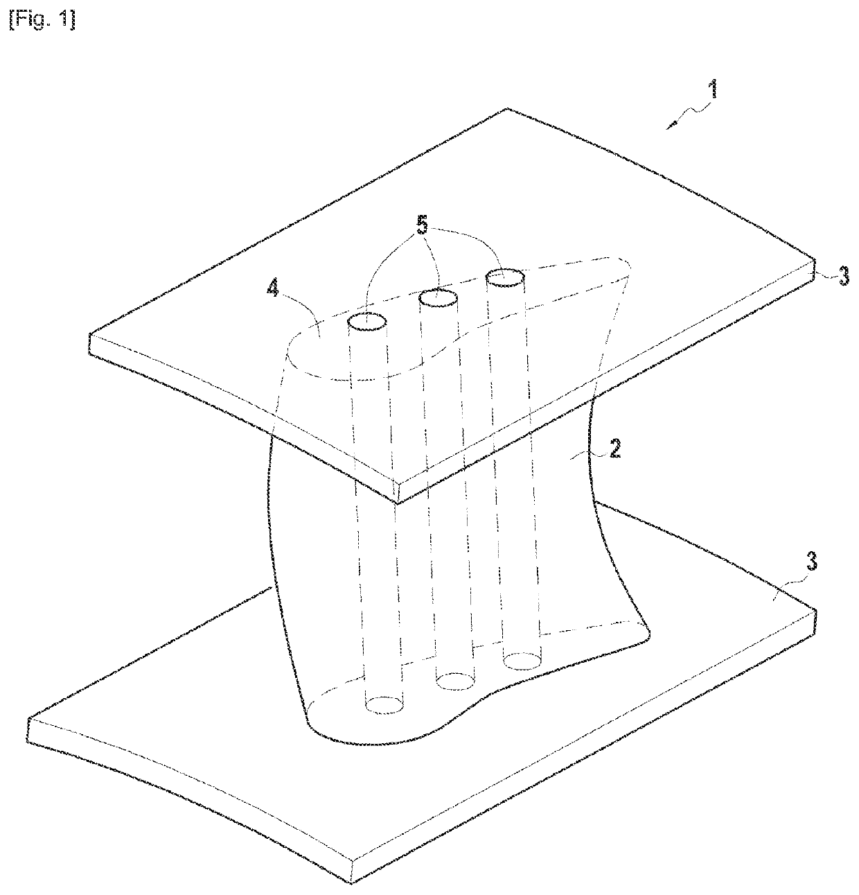
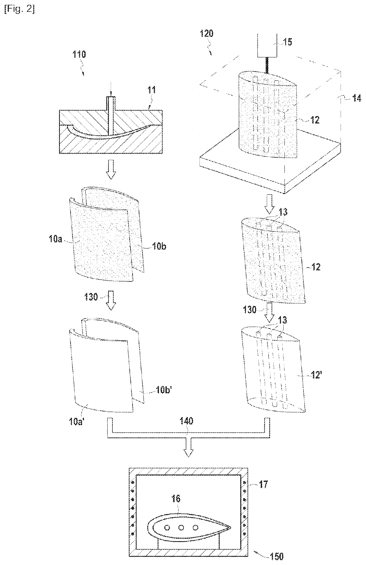
[0021]FIG. 2 illustrates very schematically the different steps of a method according to the invention. For greater clarity, the manufacture of an assembly comprising the internal portion 4 of the blade, comprising the cooling channels 5, and the aerodynamic profile 2, has been illustrated without the platforms 3. The platforms 3 can be obtained for example in the same manner as the aerodynamic profile 2.

[0022]In a first step 110, two blanks 10a and 10b are formed of two halves of the aerodynamic profile 2 by injection molding of a mixture comprising a first metal powder and a first binder. Each blank 10a and 10b corresponds in this example, to a pressure side face and a suction side face of the blade 1 and thus form two shells which, once assembled, can form the aerodynamic profile 2 of the blade 1.

[0023]To produce a blank 10a or 10b, the mixture, which has previously been brought to a temperature sufficient for injection, is injected into a mold 11, and the temperature of the mold...

second embodiment

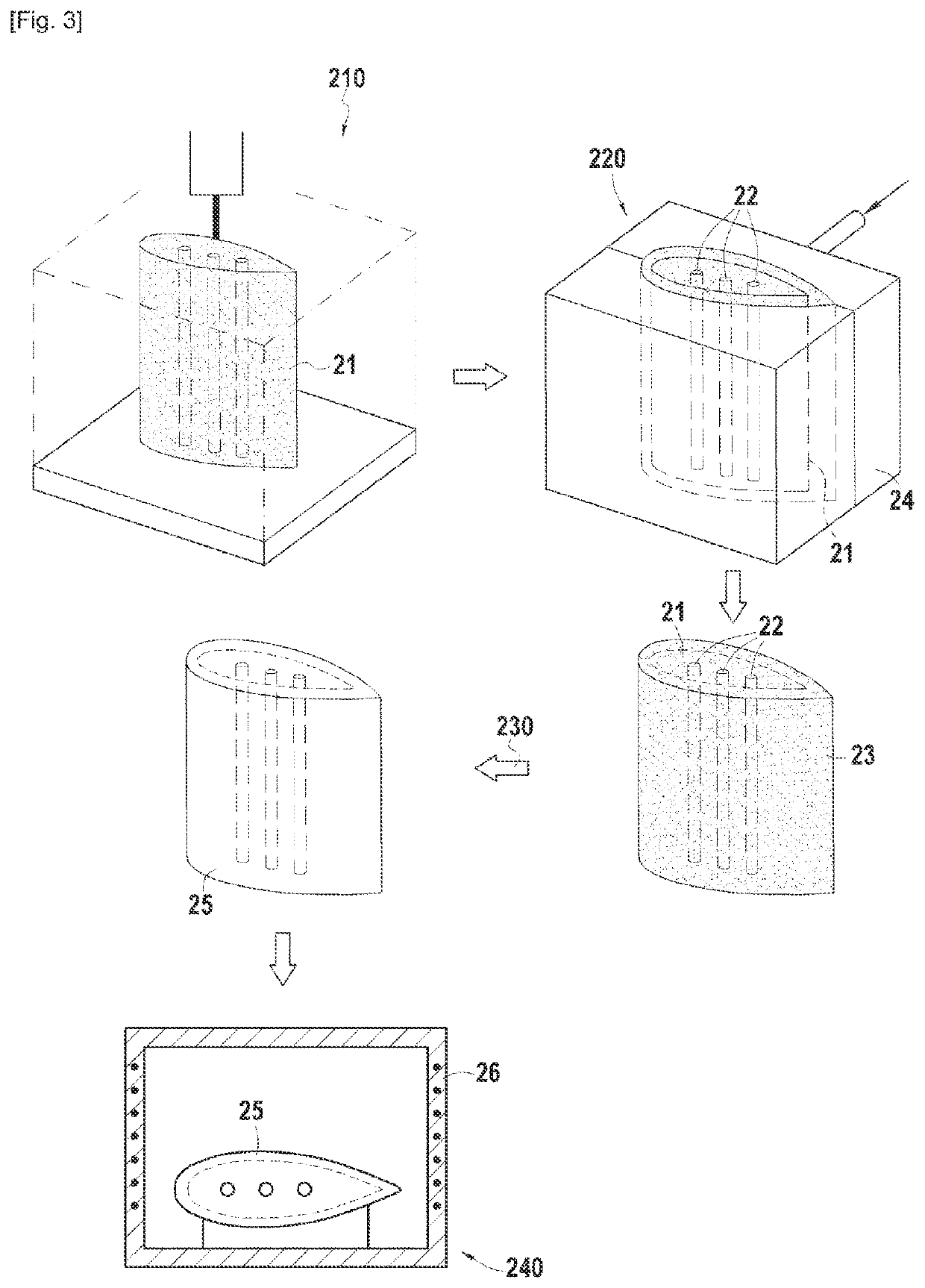
[0033]FIG. 3 illustrates the different steps of a method according to the invention.

[0034]In a first step 210 identical to the step 110, a blank 21 of the internal portion 4 of the blade 1 is formed by additive manufacturing, comprising cooling channels 22.

[0035]In a second step 220, a blank 23 of the aerodynamic profile 2 of the blade 1 is formed by injection molding. More precisely, the blank 23 of the aerodynamic profile 2 is overmolded directly over the blank 21 of the internal portion 4 of the blade 1. To this end, a mold 24 having the shape of the blade 1 to be manufactured is obtained in which is arranged the blank 21 of the internal portion 4, then the mixture comprising a metal powder and a blinder is injected. The mold 24 thus has dimensions greater than those of the blank 21. After this step, an assembly is obtained comprising the blanks 21 and 23 in the green condition which are in contact, and the blank 23 is overmolded by the blank 21.

[0036]In a step 230, identical to ...


PUM

PropertyMeasurementUnit
Aerodynamicaaaaaaaaaa

Abstract

A method for manufacturing a metal part includes forming by additive manufacturing a blank of a first portion of the part to be manufactured including a first binder and a first metal powder present in the first binder, forming by injection molding a blank of a second portion of the part to be manufactured including a second binder and a second metal powder in the second binder, debinding the blank of the first portion and the blank of the second portion, and joint sintering of the first debound blank and of the second debound blank to obtain the part, the first and the second blanks being in contact during sintering.

Description

TECHNICAL FIELD[0001]The invention relates to the general field of manufacturing methods for metal parts. It applies in particular to the manufacture of metal parts for aeronautics.PRIOR ART[0002]To produce parts in large numbers and at reduced cost, the method of injection molding of metal powder (or MIM for “Metal Injection Molding”) is known. In this known method, a mixture is formed comprising a metal powder and at least one binder, the mixture is injected in the softened state into a mold having the shape of the part to be manufactured to obtain, after demolding, a blank of the part, the blank is debound and the sintering of the debound blank is carried out to obtain the part.[0003]This method, although it is effective for manufacturing a large number of parts, does not allow the manufacture of parts having complex geometries, such as for example the cooling channels of an aeronautical turbomachine blade. There exists therefore a need for a manufacturing method which allows man...

Claims


Application Information

Patent Timeline
IPC IPC(8): B22F7/06B33Y10/00B33Y80/00B22F10/28B22F3/22B22F5/04
CPCB22F7/06B33Y10/00B22F5/04B22F10/28B22F3/225B33Y80/00B22F10/10B22F3/10B22F2998/10B22F10/00Y02P10/25
Inventor SISTACH, HUGO
Owner SN DETUDE & DE CONSTR DE MOTEURS DAVIATION S N E C M A
Why Eureka
Try Eureka