Automotive high intensity discharge lamp ballast circuit

Active Publication Date: 2006-09-07
INFINEON TECH AMERICAS
View PDF10 Cites 51 Cited by
  • Summary
  • Abstract
  • Description
  • Claims
  • Application Information

AI Technical Summary

Benefits of technology

[0026] a warm up profile circuit for causing an overdrive of the lamp for providing a high light output im

Problems solved by technology

This solution typically requires a large number of control ICs resulting in a high component count, large

Method used


Image

  • Automotive high intensity discharge lamp ballast circuit
  • Automotive high intensity discharge lamp ballast circuit
  • Automotive high intensity discharge lamp ballast circuit

Examples


Embodiment Construction

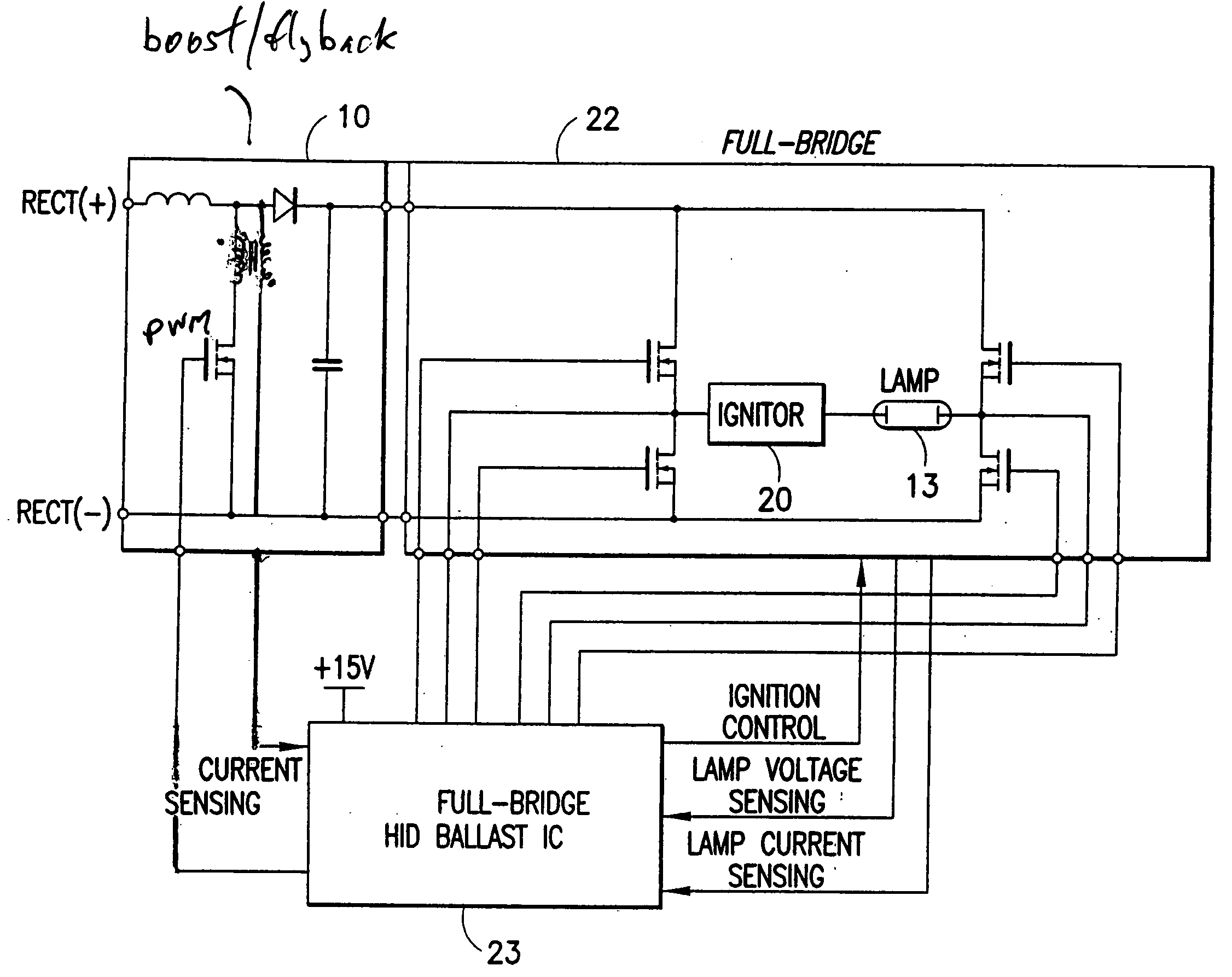
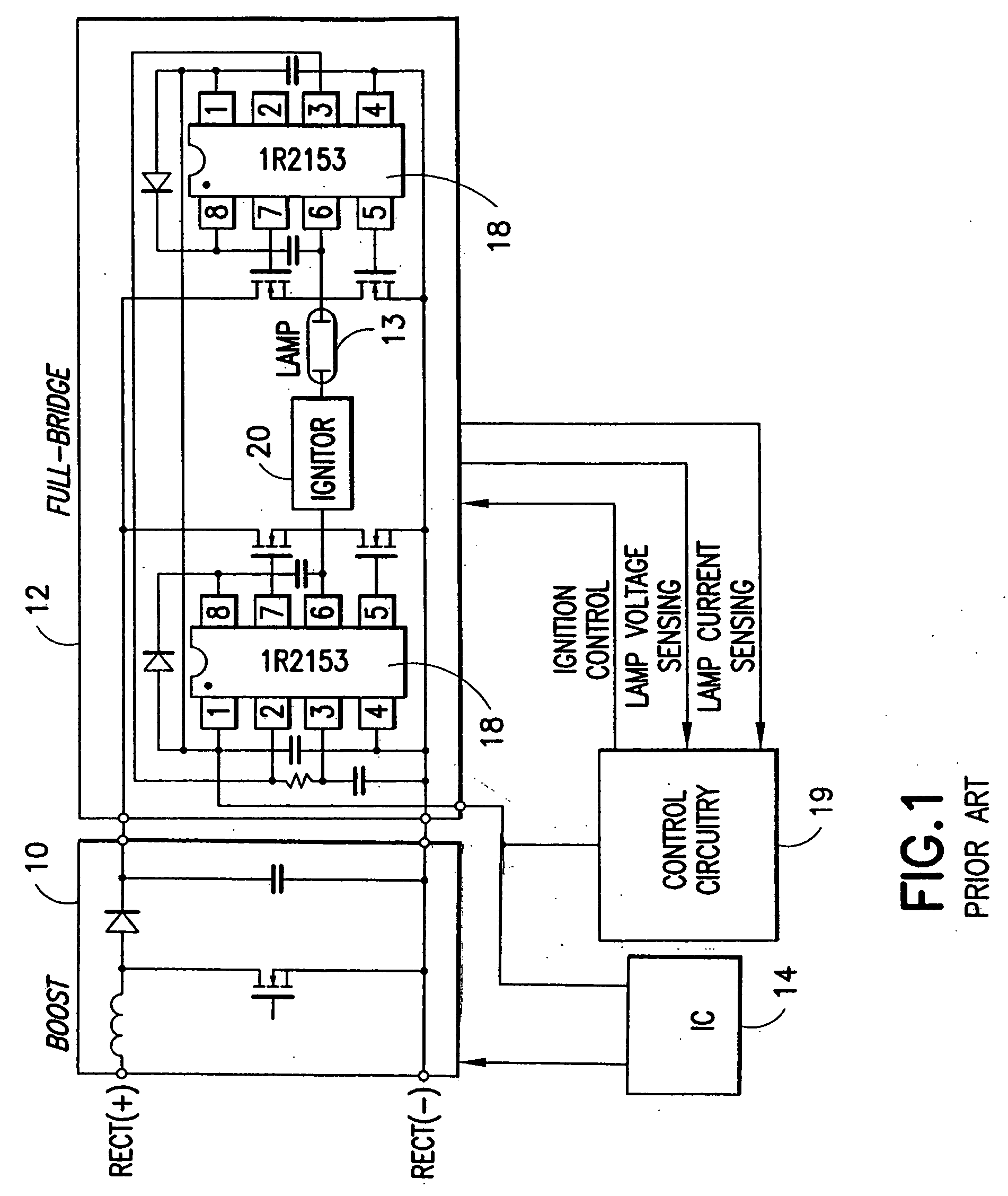
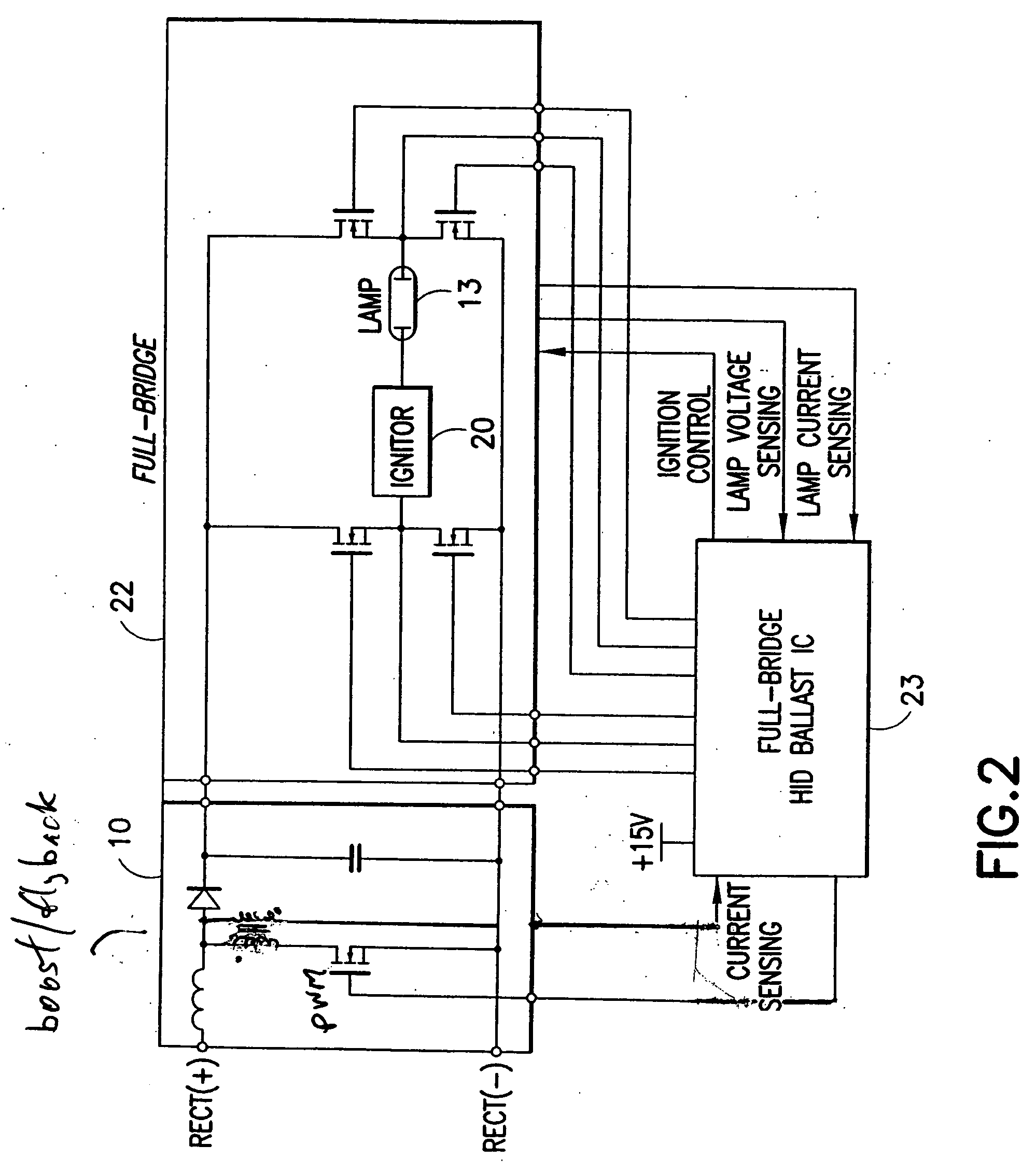
[0040] The HID control IC 23 shown in FIG. 2 provides necessary circuitry for controlling the DC bus voltage provided to the full bridge inverter stage by controlling an input boost / flyback converter at the input of the ballast, for ignition and warm-up control, for normal or running operation full-bridge control of the ballast, and fault protection. FIG. 4 illustrates how the IC 23 controls a quasi-resonant flyback converter at the input stage of the ballast, drives the full-bridge 22 for the HID lamp, controls lamp power during warm-up and running modes, sets the ignition and warm-up profile counter times and provides fault protection against open-load and short-circuit conditions. In another embodiment, an interface to an external MCU for programming is also provided (FIG. 5).

Flyback Converter Control

[0041] In a preferred embodiment of the invention shown in FIG. 4, the ballast includes a quasi-resonant flyback converter circuit 21. Although a flyback converter circuit is show...


PUM


Abstract

An electronic ballast for driving a high intensity discharge (HID) lamp is provided. The electronic ballast includes a voltage boost stage for receiving a DC input voltage and outputting a boosted DC output voltage with a controlled current. It further includes a switching stage for converting the boosted DC output voltage to a switched AC voltage capable of driving the HID lamp. An integrated circuit (IC) is coupled to the voltage boost stage and the switching stage for controlling both. The IC includes a lamp power control circuit comprising a sensing circuit for sensing an output current from the switching stage and the boosted DC output voltage, a current control loop which controls the lamp power if the lamp current is at a maximum level and a power control loop which controls the lamp power if the lamp current is below a maximum level. The IC also includes a controller unit interface and provides an ignition mode and a regular operation mode.

Description

CROSS-REFERENCE TO RELATED APPLICATION [0001] The present application claims the priority and benefit of U.S. Provisional Application Ser. No. 60 / 658,615 filed Mar. 4, 2005 entitled AUTOMOTIVE HID CONTROL IC, the entire contents of which are hereby incorporated by reference.BACKGROUND OF THE INVENTION [0002] The present invention relates to powering high intensity discharge (HID) lamps, and more particularly, to a novel circuit for continually monitoring and adjusting lamp current and voltage. [0003] First automobiles of the late 1800s were not equipped with headlights. Automobile headlights were added in 1885 to allow travel in the evening hours. The first electric headlamps appeared in 1905 and eventually became the norm. Sealed beam headlights were used into the 1970s and replaced by halogen headlamps in the 1980s and '90s. At present, the halogen headlights are being replaced by HID (High Intensity Discharge) lamps. [0004] The HID lamp provides a high-intensity light produced fr...

Claims


Application Information

Patent Timeline
IPC IPC(8): H05B41/36
CPCH05B41/2885H05B41/2886H05B41/2887H05B41/382Y02B20/202Y02B20/204Y02B20/00H05B41/24H05B41/36
Inventor RIBARICH, THOMAS J.GREEN, PETER
Owner INFINEON TECH AMERICAS
Why Eureka
Try Eureka