Shadow mask for cathode ray tube (CRT)

a technology shadow mask, which is applied in the direction of cathode ray tube/electron beam tube, electric discharge tube, electrical apparatus, etc., can solve the problems of deterioration of brightness and white uniformity of the crt, light emission, color and contrast of the crt, etc., to minimize the light emission of incorrect colors and improve brightness and white uniformity

Inactive Publication Date: 2006-10-19
SAMSUNG SDI CO LTD
View PDF6 Cites 0 Cited by
  • Summary
  • Abstract
  • Description
  • Claims
  • Application Information

AI Technical Summary

Benefits of technology

[0027] With this structure, the shadow mask for a CRT can improve brightness and white uniformity by minimizing light emission of incorrect colors.

Problems solved by technology

Accordingly, the light emission pattern of the phosphors which receive the electron beams is not the exact shape of a rectangle, and the brightness and the white uniformity of the CRT are deteriorated due to the distortion of the pattern.
Accordingly, light emission of incorrect colors occurs, and the purity of the color and the contrast of the CRT are deteriorated.
But if the bulging portion is too large, the shape of the electron beams passing through the beam passage hole also becomes large.
On the other hand, if the bulging portion is too small, it is hard to prevent the electron beams from colliding with the inner surface of the beam passage hole.

Method used


Image

  • Shadow mask for cathode ray tube (CRT)
  • Shadow mask for cathode ray tube (CRT)
  • Shadow mask for cathode ray tube (CRT)

Examples


Embodiment Construction

[0040] The present invention is described more fully hereinafter with reference to the accompanying drawings, in which exemplary embodiments of the present invention are shown.

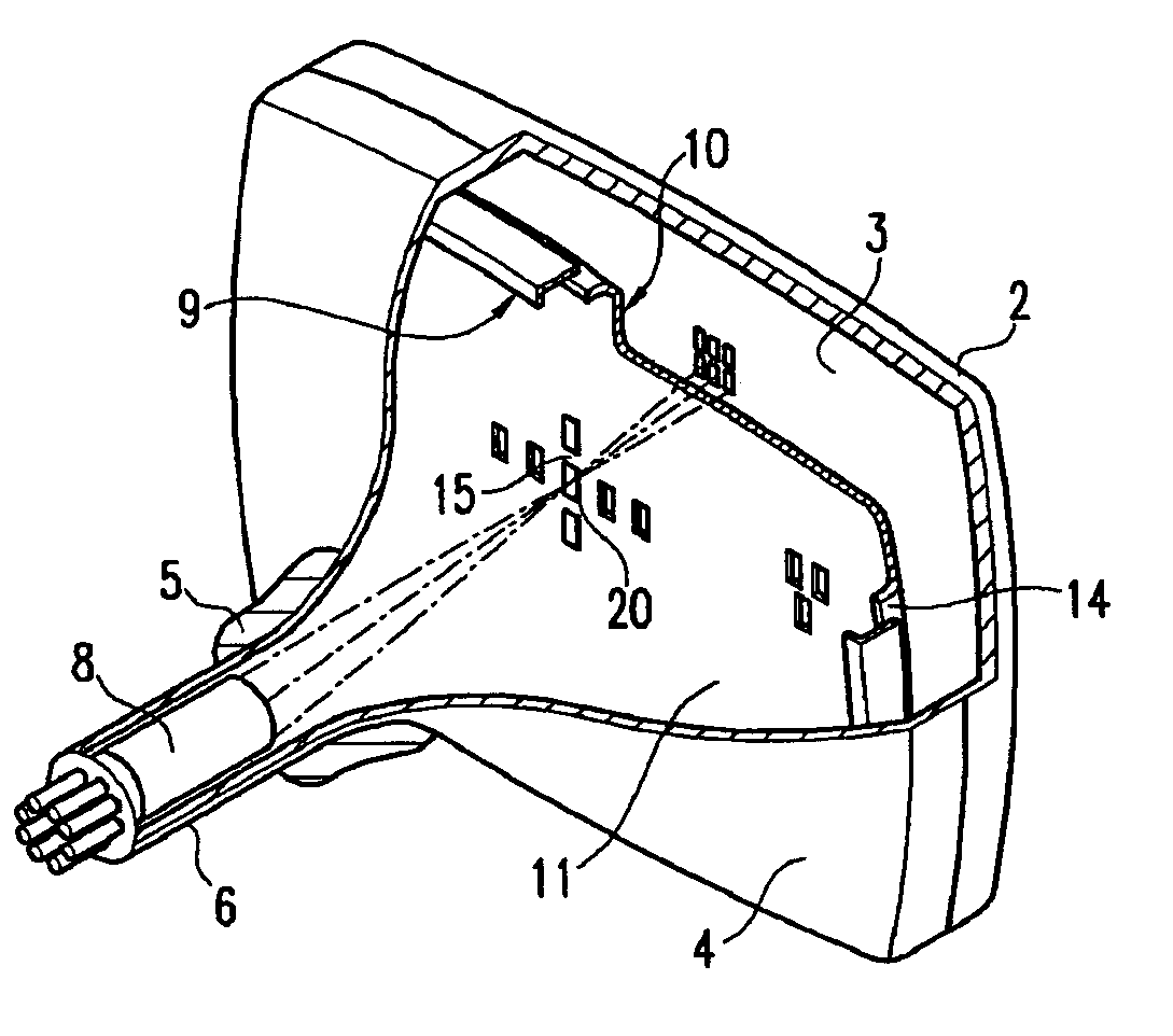
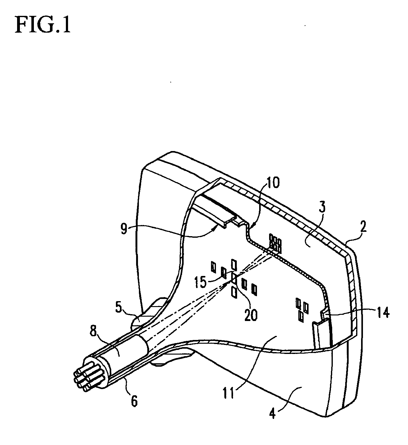
[0041] As shown in FIG. 1 and FIG. 2, a Cathode Ray Tube (CRT) with a shadow mask according to a first embodiment of the present invention includes a vacuum vessel having a panel 2, a funnel 4, and a neck 6, and an electron gun 8. A deflection yoke 5 is arranged on the vacuum vessel.

[0042] A phosphor film 3 is formed on an inner surface of the panel 2 with red R, green G, and blue B phosphors patterned while interposing a black matrix BM.

[0043] The electron gun 8 is contained within the neck 6 to emit electrons, and the deflection yoke 5 is arranged around an outer circumference of the funnel 4 to deflect the electron beams emitted by the electron gun 8.

[0044] The panel 2, the funnel 4, and the neck 6 are integrated into one body to form a vacuum vessel.

[0045] A shadow mask 10 is installed in the panel 2 ...


PUM


Abstract

A shadow mask for a Cathode Ray Tube (CRT) which achieves a high brightness and white uniformity by minimizing light emission of incorrect colors, includes: an effective screen portion with a plurality of beam passage holes arranged in a predetermined pattern and a non-holed portion surrounding the effective screen portion with no beam passage holes. The beam passage holes have a large-sized hole portion on a side facing a panel of the CRT and a small-sized hole portion that is smaller than the large-sized hole portion on a side facing an electron gun are selected such. A concave portion is formed on each of the beam passage holes arranged in a direction from a center of the effective screen portion to a direction of emission, and the concave portion is varied from the center of the effective screen portion diagonally such that a serif width D satisfies D=a−bx+cx2 (wherein a, b, and c are constants, and x is a spatial distance from the center of the effective screen portion to the center of the beam passage hole) and a, b, and c are selected such that {c/(b+c)} has an absolute value between 0.0092 and 0.0099.

Description

CLAIM OF PRIORITY [0001] This application makes reference to, incorporates the same herein, and claims all benefits accruing under 35 U.S.C. § 119 from an application for SHADOW MASK FOR CATHODE RAY TUBE earlier filed in the Korean Intellectual Property Office on the 15th of Apr. 2005 and there duly assigned Serial No. 10-2005-0031389. BACKGROUND OF THE INVENTION [0002] 1. Field of the Invention [0003] The present invention relates to a shadow mask for a Cathode Ray Tube (CRT), and more particularly, to a shadow mask for a CRT which can improve the brightness and the white uniformity and minimize the light emission of incorrect colors. [0004] 2. Description of the Related Art [0005] Generally, a Cathode Ray Tube (CRT) is an electronic tube where electron beams emitted from an electron gun are deflected due to a deflection magnetic field, pass through a color selection shadow mask, and then strike and excite green, blue, and red phosphors on a phosphor film within a panel, thereby di...

Claims


Application Information

Patent Timeline
Patent Type & Authority Applications(United States)
IPC IPC(8): H01J29/80
CPCH01J29/076H01J2229/0788H01J2229/0755H01J29/07
Inventor PYUN, DO-HUNJEONG, SOON-DONGSHIN, SOON-CHEOLKIM, HOO-DEUKKIM, MUN-SEONG
Owner SAMSUNG SDI CO LTD
Why Eureka
Try Eureka