Card socket assembly

a card socket and socket technology, applied in the direction of electrical apparatus casings/cabinets/drawers, coupling device connections, instruments, etc., can solve the problems of excessive stress, sockets or brackets may be damaged or deformed, excessive stress, etc., to achieve smooth card inserting, stably holding the socket, and efficient utilization of space

a card socket and socket technology, applied in the direction of electrical apparatus casings/cabinets/drawers, coupling device connections, instruments, etc., can solve the problems of excessive stress, sockets or brackets may be damaged or deformed, excessive stress, etc., to achieve smooth card inserting, stably holding the socket, and efficient utilization of space

US20060250757A1Inactive Publication Date: 2006-11-09HIROSE ELECTRIC GROUP

Image

  • Card socket assembly
  • Card socket assembly
  • Card socket assembly

Examples


Embodiment Construction

[0019] Hereunder, embodiments of the present invention will be explained with reference to the accompanying drawings.

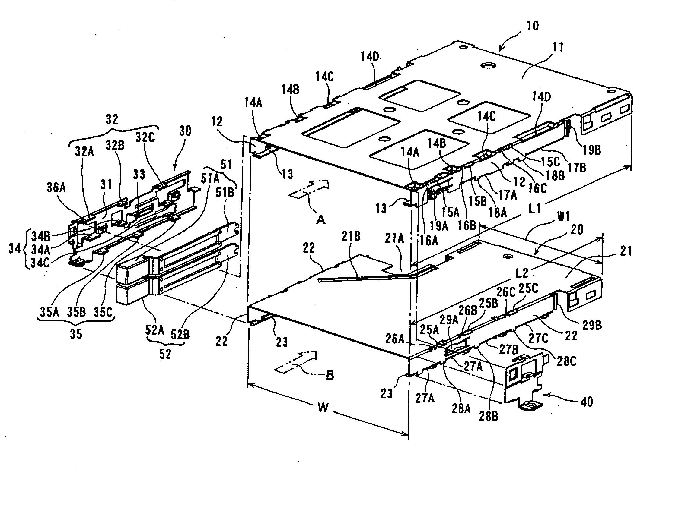
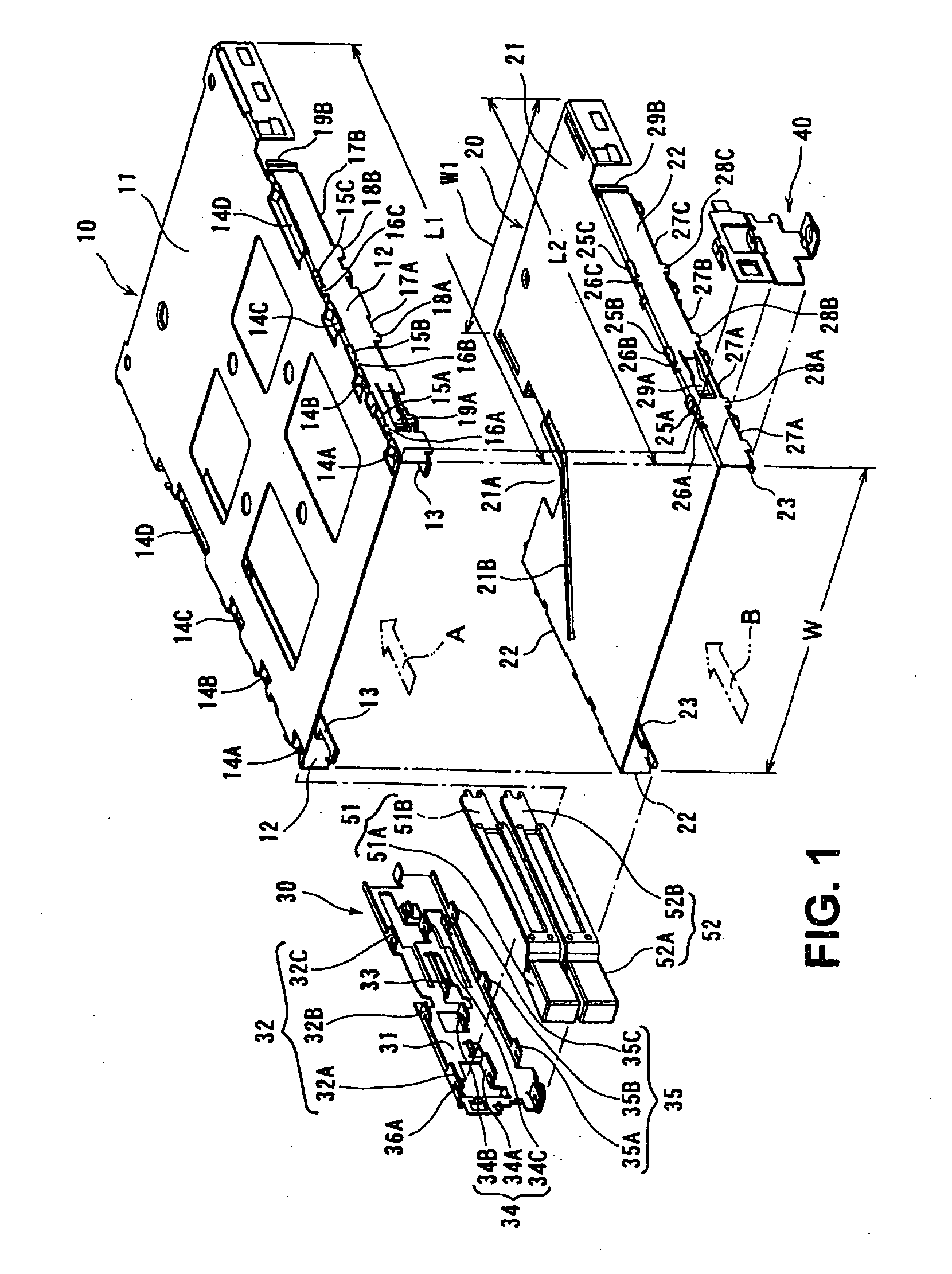
[0020]FIG. 1 is an exploded perspective view showing a card socket assembly according to an embodiment of the present invention.

[0021] As shown in FIG. 1, a PC card socket 10 is situated at an upper stage, and an express card socket 20 is situated at a lower stage. The upper socket 10 and the lower socket 20 have inner dimensions corresponding to a PC card and an express card to be inserted from arrow directions A and B, respectively. That is, the upper socket 10 and the lower socket 20 have a same inner dimension W in a width direction as a card inlet, and different inner dimensions L1 and L2 in the arrow directions A and B, respectively. The inner dimension L1 is larger than the inner dimension L2.

[0022] The upper socket 10 is manufactured by punching and bending a metal plate, and has a symmetrical shape in a left-to-right direction relative to a center line ext...


PUM


Abstract

A card socket assembly includes a plurality of sockets situated in multiple stages for receiving cards and a pair of fixing members disposed at both sides of the sockets for fixing the sockets to a circuit board. Each of the fixing members includes a fixing portion to be fixed to the circuit board and a holding portion for holding the socket. The holding portion of one of the fixing members includes a first holding member for holding all of the sockets. The holding portion of the other of the fixing members includes a second holding member for holding one of the sockets and an elastic holding member for holding the others of the sockets separately and elastically.

Description

BACKGROUND OF THE INVENTION AND RELATED ART STATEMENT [0001] The present invention relates to a card socket assembly. [0002] An electric device, especially a personal computer, is provided with a socket for receiving a card such as a PC card to expand functionality. Such a socket corresponds to a specific card, and a plurality of sockets is supported integrally with a bracket to form a card socket assembly. [0003] Patent Reference has disclosed brackets for supporting two sockets for receiving cards. The brackets are formed of metal, and are situated at left and right sides of the sockets. Each of the brackets includes a fixing portion contacting with a circuit board and a holding portion contacting with a side of the socket. The fixing portion and the holding portion are bent to have an L shape cross-section. [0004] In the bracket disclosed in Patent Reference, the holding portion has an opening portion, so that an engaging portion with a tongue shape provided on the socket slides ...

Claims


Application Information

Patent Timeline
09 Nov 2006
Publication
US20060250757A1
IPC
H02B1/00; H01R12/50
CPC
G06F1/185; H01R12/7047; H05K5/0286
Inventors
EZAKI, MASAKAZU