Stapler capable of cutting staple legs

Inactive Publication Date: 2006-11-30
APEX MFG
View PDF31 Cites 16 Cited by
  • Summary
  • Abstract
  • Description
  • Claims
  • Application Information

AI Technical Summary

Benefits of technology

[0007] The primary advantage of the stapler according to the present invention is its low cost because it does not require hig

Problems solved by technology

Several problems have been encountered in using this conventional staple.
However, such precise location requires precise fabrication and assembly an

Method used


Image

  • Stapler capable of cutting staple legs
  • Stapler capable of cutting staple legs
  • Stapler capable of cutting staple legs

Examples


Embodiment Construction

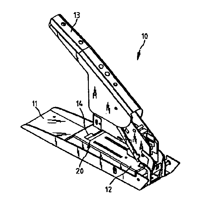
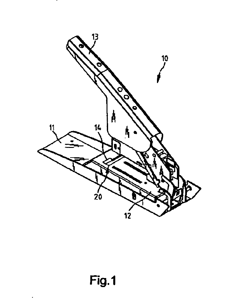
[0018] Referring to FIGS. 1 and 2, according to the preferred embodiment of the present invention, a stapler 10 includes a base 11, a cover 12 provided on the base 11 a feeding device for feeding staples 30 each including two legs 31 (FIG. 5), a connecting device for connecting the base 11, the cover 12 and the feeding device with one another, and a bending and cutting device 20 for bending and cutting the legs 31. The base 11, the cover 12, the feeding device and the connecting device, and their interconnection are substantially conventional and will not be described in detail. The feeding device includes a cartridge 14 for storing the staples 30 and a lever 13 for moving the cartridge 14, driving the staples 30 from the cartridge 14 and moving the cover 12.

[0019] Referring to FIGS. 3 through 5, the bending and cutting device 20 includes a first shell 21, a second shell 22, two movable cutting elements 23, a spring 27, two bending elements 24, a stationary cutting element 25, and ...


PUM


Abstract

A stapler includes a base, a cover put movably on the base, a feeding device for feeding staples, and a bending and cutting device provided between the base and the cover for bending and cutting the legs of each staple. The cutting device includes a seat provided on the base and a housing attached to the cover. The seat includes two wedges formed thereon and a pusher formed thereon. A stationary cutting element is provided in the housing. Two movable cutting elements are provided movably in the housing and on the two wedges so that they are moved towards the stationary cutting element in order to cut the legs of each staple as they are moved towards the seat together with the housing. A spring is put between the movable cutting elements in a tendency to push the movable cutting elements from the stationary cutting element. Two bending elements are provided movably and pivotally in the housing above the movable cutting elements so that they are pushed by the pusher in order to bend the legs of each staple after the stationary cutting element and the movable cutting elements cut the legs of each staple.

Description

BACKGROUND OF INVENTION [0001] 1. Field of Invention [0002] The present invention relates to a stapler and, more particularly, to a stapler capable of cutting staple legs. [0003] 2. Background of Invention [0004] WO 03 / 057417 A1 discloses a STAPLER WITH BENDING ARMS WHICH CUT THE STAPLER LEGS AGAINST A PAD. The stapler includes two bending arms 40 and 41 and a cutter 49. The bending arm 40 is pivotally provided by means of a pin 42. The bending arm 40 includes a lever 45 on a side of the pin 42 and a bending surface 44 on the other side of the pin 42. The bending arm 41 is pivotally provided by means of a pin 43. The bending arm 41 includes a lever 48 on a side of the pin 43 and a bending surface 47 on the other side of the pin 43. The cutter 49 includes two cutting edges 50 and 51. The cutter 49 is located between the bending surfaces 44 and 47. As the levers 45 and 48 are pivoted, the bending surfaces 44 and 47 bend and press stapler legs 53 and 54 against the cutting edges 50 and...

Claims


Application Information

Patent Timeline
IPC IPC(8): B25C7/00
CPCB25C5/0207
Inventor TSAI, ERIC
Owner APEX MFG
Why Eureka
Try Eureka